Table of Contents
Advertisement
Quick Links
EN
Technical information
Installation instructions
Oil/gas boiler
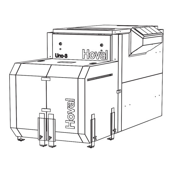
Uno-3 (130-280)
Hoval products must be installed and commis-
sioned only by appropriately qualifi ed experts.
These instructions are intended exclusively for
the specialist. Electrical installations may only
be carried out by a qualifi ed electrician.
This manual is valid for the following types:
7-Uno-3 (130, 160, 190, 220, 250, 280)
7-Uno-3 b-i * (130, 160, 190, 220, 250, 280)
and for the same types with increased opera-
ting pressure (H)
* = burner integrated
Uno-3 (130-280) boilers are suitable and
licensed for use as heat generators for hot water
heating systems with a permissible flow tempe-
rature of up to 100°C
1)
closed-circuit systems, but can also be installed
in open systems as per EN 12828.
see point 3.2
1)
4 205 118 / 01 - 08/09
. They are designed for
Subject to modifi cations
Advertisement
Table of Contents

Subscribe to Our Youtube Channel
Related Manuals for Hoval Uno-3


Summary of Contents for Hoval Uno-3
- Page 1 This manual is valid for the following types: 7-Uno-3 (130, 160, 190, 220, 250, 280) 7-Uno-3 b-i * (130, 160, 190, 220, 250, 280) and for the same types with increased opera- ting pressure (H)
-
Page 2: Table Of Contents
Technical information Description of the boiler ........................12 3.1.1 The Uno-3 (130-280) complies with the following directives + standards ..........12 Technical data Uno-3 (130-280) ......................13 Dimensions ............................14 Dimensions without heat insulation and casing (transport dimensions) ........14 Installation Boiler room requirements ........................ -
Page 3: Important Information
- DIN 57 116 / VDI 0116 Electrical equipment in All instructions relevant to your system can be found combustion systems (VDE regulations). in the Hoval system manual! In exceptional cases, - For further standards applicable in Germany, see the instructions can be found enclosed with the supplement N-430 020. -
Page 4: Warranty
Important information 4 205 118 / 01 Warranty Fault-free operation can only be guaranteed if these instructions and the instructions in the operating manual are followed and if the boiler is regularly serviced by a licensed specialist. (service contract). The rectification of faults and damage resulting from the use of contaminated operating materials (gas, water, combustion air), unsuitable chemical additives to the heating water, improper handling, faulty instal-... -
Page 5: Assembly
There must be enough space to swing open the boiler door, incl. the burner. Installation position Where limited space is available, the Uno-3 can Boiler door pivotable to the left be transported standing on the door. Hex nuts are It is possible to change the attachment of the boiler mounted behind the door as supports for this purpose. -
Page 6: Fitting The Heat Insulation
Assembly 4 205 118 / 01... - Page 7 Assembly 4 205 118 / 01...
-
Page 8: Fitting The Casing
Assembly 4 205 118 / 01... - Page 9 Assembly 4 205 118 / 01...
-
Page 10: Fitting The Boiler Controller At The Top
Assembly 4 205 118 / 01 Fitting the boiler controller at the top Remove controller box cover plate (15, Figure 7). The control panel (15a, Figure 7a) must be turned around. To do this, remove the pressure lock sleeves (15b, press together and pull off) and the earthing screw and serrated washer (15c). - Page 11 Assembly 4 205 118 / 01 Fig. 7...
-
Page 12: Technical Information
Description of the boiler The flue gas temperatures can be varied within a The Uno-3 is a threepass boiler. At the end of the specific range through the installation of various re- circular cylindrical combustion chamber, the flame gulator combinations. -
Page 13: Technical Data Uno-3 (130-280)
At nominal output, the pollutant limit values and flue gas losses as per regulation LRV (92) are complied with. Controller U3.1 and T2.2 Controller U3.2 and T2.2 Flow resistance boiler in mbar = flow rate (m Data valid for Hoval oil compact heat station b-i Possible operating conditions Fuel Heating oil EL... -
Page 14: Dimensions
195 675 950 1218 310 596 249 178 1535 76 *q = flue gas outlet external diameter. Plate thickness 3 mm; adapter set for Uno-3 (250-280): D qø 199, A qø 200 (with tape) Dimensions without heat insulation and casing (transport dimensions) Boiler (without calorifier) incl. -
Page 15: Installation
Installation 4 205 118 / 01 Installation Existing flue gas systems may require up- Boiler room requirements grading or adjustment of the flue duct cross- Regarding the building specifications for boiler rooms section as indicated by a chimney engineer. and their supply and extract air handling, the current building supervisory office regulations specific to the The correct functioning of the flue duct, i.e. - Page 16 In Switzerland, SIA recommendation 384/4 must be observed! In Austria, calculation is performed as prescribed by ÖNorm M 7515. Non-binding guide values for dimensioning of the flue duct for boiler types Uno-3 (130-280). Inside diameter of flue duct in mm Boiler type Chimney Uno-3...
-
Page 17: Fitting The Burner
Installation 4 205 118 / 01 Fitting the burner Fig. 11 Uno-3 L max Ø Ø Ø Ø 130-160 220/270 190-220 250-280 1434 - Depending on the size of the burner flange, an intermediate flange may be required to attach the burner. -
Page 18: Fuel
The installer can change the flue gas regulator set fitted and thus vary the flue gas temperature within Uno-3 boilers are suitable for the combustion of the a specific range. following fuels: - Heating oil EL in accordance with DIN 51 603 / SN... -
Page 19: Flue Gas And Performance Diagrams
Installation 4 205 118 / 01 4.6.1 Flue gas and performance diagrams Uno-3 (130) for Switzerland only 9R3/290 105 110 120 125 Uno-3 (160) 6R5/290 85 90 95 100 105 110 115 120 125 130 135 140 145 150 155 160... - Page 20 Installation 4 205 118 / 01 Abgastemp. 6-Uno-3 130-280 Uno-3 (250) 6R5 + 3R3/290 150 160 170 180 190 200 210 220 230 240 250 Abgastemp. 6-Uno-3 130-280 Uno-3 (280) Seite 1 6R5 + 6R2/290 160 170 180 190 200 210 220 230 240 250 260 270 280...
-
Page 21: Flow Mixing Loop / Minimum Limitation Of The Boiler Return Temperature
Installation 4 205 118 / 01 Flow mixing loop / minimum limitati- on of the boiler return temperature Hydraulic and control measures must be provided to ensure that the temperatures do not fall below the permissible minimum boiler flow and return tempe- rature under any operating conditions. -
Page 22: Commissioning
8.3 and 9.5 after 6-12 weeks of heating op- In particular, attention must be paid to the following eration. stipulations: • Hoval boilers and calorifi ers are designed for heat- ing plants without signifi cant oxygen intake (plant Filling and replacement water type I according to EN 14868). -
Page 23: Filling The Heating System
Commissioning 4 205 118 / 01 Filling the heating system Filling of the heating system must be carried out by trained personnel. The filling and replacement water must comply with the quality requirements in the relevant state or country (VDI 2035 or SWKI 88-4 or ÖNORM H 5195). -
Page 24: Maintenance
Maintenance 4 205 118 / 01 Maintenance Information for fire inspector / chimney sweep regarding emission monitor key All other control elements of the control unit are described in the operating instructions. The emission monitor key can also be used to change over to manual operating mode. Emission monitor key / Manual operation To protect under fl oor heating systems against... -
Page 25: Cleaning
Maintenance 4 205 118 / 01 Cleaning Cleaning should be performed at least twice per year. Cleaning at intermediate intervals is necessary if the flue gas temperature rises. 6.2.1 Preparatory work - Switch boiler off (controller: set switch to "O," pull the burner plug) - Interrupt the fuel supply - Open the boiler door... -
Page 26: Overview Of Settings
Overview of settings 4 205 118 / 01 Overview of settings Table of parameters Regulator Setting range / Designation Factory Setting values Type of device: DHW: Address: Surface operation Key : Heating curve HC OFF, 0,20 ..3,5 Heating curve MC1 OFF, 0,20 .. - Page 27 Overview of settings 4 205 118 / 01 Table for Time programs DHW circuit Time program P1 Time program P2 Time program P3 Cycle 1 Cycle 2 Cycle 3 Cycle 1 Cycle 2 Cycle 3 Cycle 1 Cycle 2 Cycle 3 from from from...
- Page 28 Overview of settings 4 205 118 / 01 HYDRAULIC Par. Designation Factory Lev. Function allocation of the output DHW charging pump Function allocation of the output Mixer circuit 1 Function allocation of the output Mixer circuit 2 Function allocation of the output Direct circuit Pump Function allocation of the variable output 1 Function allocation of the variable output 2 OFF/ 4/ 43...
- Page 29 Overview of settings 4 205 118 / 01 Par. Designation Factory Lev. DHW-NIGHT DHW - economy temperature 40/ 45 °C DHW-legionella protection-day DHW-egionella protection-time 2:00 50/ 55/ 65/ DHW-legionella protection-temperature 70 °C DHW-temperature recording 50/ 55/ 65/ DHW-maximum temperature limit 70 °C DHW-mode of operation DHW-tank discharge protection...
- Page 30 Overview of settings 4 205 118 / 01 MIX. VALVE-1 Par. Designation Factory Lev. Type of reduced operation ECO/ ABS Heating system (exponent) MK= 1,10 Room override (in connection with room sensor) Room factor 100 % Adaptation heating curve Switch-on optimisation Heating limit Room frost protection limit 10 °C...
- Page 31 Overview of settings 4 205 118 / 01 MIX. VALVE-2 Par. Designation Factory Lev. Type of reduced operation ECO/ ABS Heating system (exponent) MK= 1,10 Room override (in connection with room sensor) Room factor 100 % Adaptation heating curve Switch-on optimisation Heating limit Room frost protection limit 10 °C...
- Page 32 Overview of settings 4 205 118 / 01 HEAT GENER. Par. Designation Factory Lev. H-GEN model 1/ 2/ 5 Start-up protection H-GEN OFF/ 3 5/ 48/ 65/ 75 Minimum temperature limit H-GEN °C Maximum temperature limit H-GEN 75/ 85 °C Mode of action minimum temperature limit H-GEN Sensor mode operation for H-GEN Minimum burner running time...
- Page 33 Overview of settings 4 205 118 / 01 RETURN CONTR Par. Designation Factory Lev. Minimum limit return temperature / referance value return 38 °C temperature Switch-off difference Pump follow-on time 1 Min SOLAR Par. Designation Factory Lev. Switch-on difference 10 K Switch-off difference Minimum running time SOP 3 Min...
- Page 34 Overview of settings 4 205 118 / 01 BUFFER Par. Designation Factory Lev. Minimum temperature 5/ 20 °C Maximum temperature 95 °C Temperature elevation, H-GEN 8/ 10/ 12K Switching difference 2/ 5/ 10K Forced discharge Skimming function switch-on difference 10 K Skimming function switch-off difference Start-up protection Discharge protection...
- Page 35 Overview of settings 4 205 118 / 01 SERVICE Par. Designation Factory Lev. Service 1 (Cleaning ST1 ) Suspend message «CLEANING ST-1» for X days Cleaning according to fi xed date Cleaning according to fi xed interval Cleaning according to cleaning counter Reset cleaning display 1 Service 2 (Cleaning ST2) Suspend message «CLEANING ST-2»...
-
Page 36: Overview Of Alarms Toptronic ® T
Overview of settings 4 205 118 / 01 FAULT REPORTING OVERVIEW TopTronic ® Status Designation Fault type Code Remark System External sensor Interruption 10-0 System External sensor Short-circuit 10-1 System Boiler sensor Interruption 11-0 System Boiler sensor Short-circuit 11-1 System Flow sensor 1 Interruption 12-0... - Page 37 Regulator with address 10 is System Activity 70-8 missing System Activity Data bus error 70-9 No Hoval regulator System HP return sensor Return min. temp. below setpoint 85-4 System HP return sensor Return max. temp. exceeded 85-5 Heat source min. temp. below...
- Page 38 4 205 118 / 01...
- Page 39 4 205 118 / 01...
- Page 40 Copy for plant user C O N F I R M A T I O N The user (owner) of the system herewith confi rms that - he has received adequate instruction in the operating and maintenance of the installation, - received and taken note of the operating and maintenance instructions and, where applicable other documents concerning the heat generator and any further components.
Need help?
Do you have a question about the Uno-3 and is the answer not in the manual?
Questions and answers