Table of Contents
Advertisement
Quick Links
Installation Instructions and Homeowner's Manual
WARNING! IF THE INFORMATION IN THIS MANUAL IS NOT FOLLOWED
EXACTLY, A FIRE MAY RESULT CAUSING PROPERTY DAMAGE, PERSONAL
INJURY OR LOSS OF LIFE.
COMFORT GLOW PHONE NUMBER: (814) 643-1775
http://www.worldmkting.com
ANSI/UL 1278. MOVABLE AND WALL-OR CEILING HUNG ELECTRIC ROOM HEATERS
INSTALLER: DO NOT DISCARD THIS MANUAL - LEAVE FOR HOME OWNER
CUSTOMER: PLEASE RETAIN THIS MANUAL FOR FUTURE USE
Comfort Home Products, Inc.
12256 William Penn Hwy, Suite A
Huntingdon, PA 16652
Made in China
Printed in China
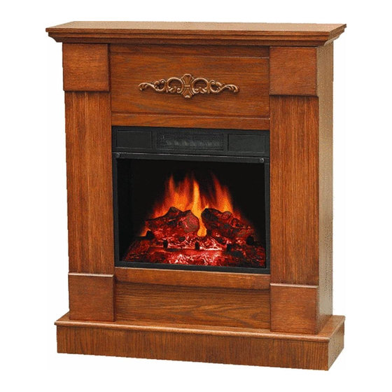
EF5528RKD
Freestanding
Electric Fireplace
FOR YOUR SAFETY
DO NOT STORE
OR USE GASOLINE OR
OTHER FLAMMABLE VAPORS
IN THE VICINITY OF THIS OR
ANY OTHER APPLIANCE
-1 -
OR LIQUIDS
Advertisement
Table of Contents

Subscribe to Our Youtube Channel
Related Manuals for Comfort Glow EF5528RKD


Summary of Contents for Comfort Glow EF5528RKD
-
Page 1: For Your Safety
Printed in China OR LIQUIDS IN THE VICINITY OF THIS OR ANY OTHER APPLIANCE COMFORT GLOW PHONE NUMBER: (814) 643-1775 http://www.worldmkting.com ANSI/UL 1278. MOVABLE AND WALL-OR CEILING HUNG ELECTRIC ROOM HEATERS INSTALLER: DO NOT DISCARD THIS MANUAL - LEAVE FOR HOME OWNER... -
Page 2: Table Of Contents
TABLE OF CONTENTS PLEASE READ THE INSTALLATION & OPERATIONS INSTRUCTIONS BEFORE USING THIS APPLIANCE IMPORTANT: Read all instructions and warnings carefully before starting installation. Failure to follow these instructions may result in a possible electric shock, fire hazard and will void the warranty. INSTALLATION INSTRUCTIONS GENERAL LOCATING YOUR ELECTRIC FIREPLACE... -
Page 3: Important Safety Instructions
IMPORTANT SAFETY INSTRUCTIONS PLEASE RETAIN THIS USER’S GUIDE FOR FUTURE REFERENCE When using electrical appliances, basic precautions should always be followed to reduce the risk of fire, electric shock, and injury to person, including following: 1. Read all instructions before using this appliance. such as a bed, where openings may become blocked. -
Page 4: General
WARNING: Procedures and WARNING: Procedures and techniques, which, if not techniques, which, if not carefully followed, will result carefully followed, will expose in damage to the equipment the user to the risk of serious or personal property or may injury, illness or death. cause personal injury. -
Page 5: Assembly Instructions
ASSEMBLY INSTRUCTIONS NOTE: A complete electric fireplace heater should consist of two parts: the wooden mantel and the fireplace heater each packed in a separate carton. It is not recommended to use the fireplace heater without the wooden mantel. Unpack the fireplace heater and mantel. Remove all packing materials. - Page 6 Step 2: Attach the SIDE PANEL (C) to the LEFT FRONT PANEL (D1) and RIGHT FRONT PANEL(D2) with 6 KD SCREWS (3 screws for each side). See Figure B. Step 3: Attach the LEFT and RIGHT SIDE PANELS (C, D, & G) to the BASE (B) using 4 KD SCREWS (2 screws for each side.) See Figure C.
- Page 7 Step 5: Attach the UPPER FRONT PANEL (E) in between the upper section of the 2 FRONT PANELS (D1, D2) with 2 KD SCREWS (1 screw for each side.) See Figure E. Step 6: Place the LOWER FRONT PANEL (F) in between the lower section of 2 FRONT PANELS (D1, D2) and attach with 2 KD SCREWS (1 screw for each side.) See figure F.
- Page 8 Step 8: Put the insert in place and install the insert to the mantel with 5 SHORT KD SCREWS and 3 mounting clips on upper side, 2 mounting bracket on lower side. See Figure H and I. -8 -...
-
Page 9: Operating Instructions
Step 9: Tighten all KD Screws. OPERATING INSTRUCTIONS Once the fireplace heater insert has been properly installed and connected to a ground electrical outlet. It is ready to operate. Note: Ensure the circuit breakers for the power supply are turned on. The controls are located behind two small flapping doors on the upper front of firebox. -
Page 10: Heater Controls
1. Main Power On/Off: Press this switch for main power. The indicator light will turn on. 2. ON/OFF: Press this button for turning on the insert PCB board power. 3. FLAME: Press this button to turn on the flame/log. Press this button again to turn off the flame. Keep pressing down this button, the flame/log light will turn from bright to dim. -
Page 11: Service Instructions
SERVICE INSTRUCTIONS WARNING: Disconnect power WARNING: Do not exceed before attempting any 40 Watts per light bulb. maintenance or cleaning to Use of a higher rated bulb reduce the risk of fire, may result in a fire electrical shock or personal causing property damage injury. -
Page 12: Instructions For Power
WARNING: Before servicing this heater be sure to unplug heater from wall outlet. Do not only turn off heater from the main “ON/OFF” switch, be sure to unplug this heater SPECIFICATIONS: MODEL: EF5528RKD VOLTAGE: 120V/60HZ TOTAL AMPS: 11.3 AMPS TOTAL WATTS: 1500W... -
Page 13: Replacement Parts List
REPLACEMENT PARTS LIST ITEM DESCRIPTION Flame Screen NDF-100NR/14 Thermostat knob NDF-100NR/78 Firebox cabinet NDF-100NR/15 Front Louver NDF-100NR/18 Flapping Door NDF-100NR/12 Touch Pad NDF-100R/88R Log Set NDF-100R/02 Power Cord/Plug NDF-100NR/89 Glass Screen NDF-100NR/41 Thermostat Control Device NDF-100NR/60 Remote Handset NDF-100NR/103 PCB Board NDF-100NR/88 Flame Reflector Assembly NDF-100NR/43,44,68,69...
Need help?
Do you have a question about the EF5528RKD and is the answer not in the manual?
Questions and answers