Chauvet Intimidator SPOT 355Z IRC User Manual
Hide thumbs
Also See for Intimidator SPOT 355Z IRC:
- Quick reference manual (93 pages) ,
- Quick reference manual (56 pages) ,
- Quick reference manual (56 pages)
Table of Contents
Advertisement
Quick Links
Download this manual
See also:
Quick Reference Manual
Advertisement
Table of Contents

Related Manuals for Chauvet Intimidator SPOT 355Z IRC


Summary of Contents for Chauvet Intimidator SPOT 355Z IRC
- Page 1 User Manual...
-
Page 2: Table Of Contents
ABLE OF ONTENTS 1. Before You Begin ................4 What Is Included ....................4 Unpacking Instructions ..................4 Claims ........................4 Text Conventions ....................4 Symbols ......................4 Document Information ..................4 Product at a Glance ..................5 Safety Notes ...................... 5 2. - Page 3 Contact Us ...................... 26 6. Technical Specifications ..............27 Intimidator™ Spot 355Z IRC User Manual Rev. 1 Page 3 of 27...
-
Page 4: Before You Begin
Chauvet assumes no responsibility or liability for any errors or omissions Information that may appear in this manual. Chauvet reserves the right to update the existing document or to create a new document to correct any errors or omissions. -
Page 5: Product At A Glance
Product at a Use on Dimmer Auto Programs Outdoor Use Auto-ranging Power Supply Glance Sound-Activated Replaceable Fuse User-Serviceable Master/Slave Safety Notes These notes include important information about the mounting, usage, and maintenance of this product; read before using the product. ·... -
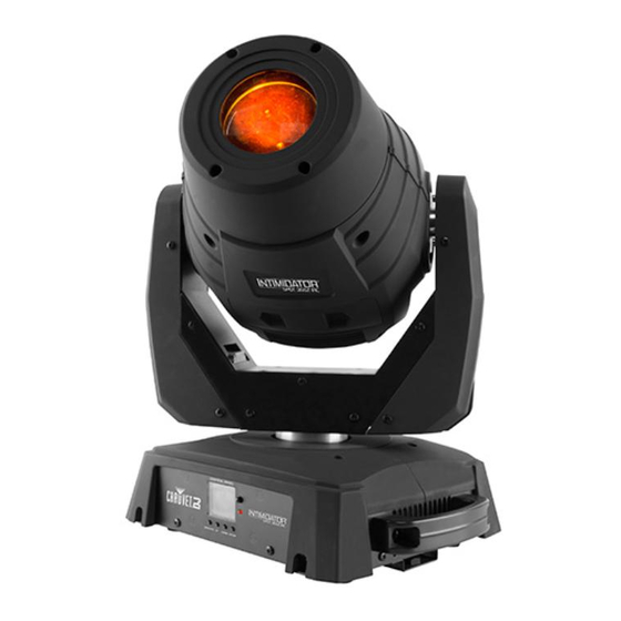
Page 6: Introduction
2. I NTRODUCTION Product Overview IR Sensor Indicator LED Control Panel and Button Menu Safety Loop DMX Out Power Out DMX In Power In Fuse Holder Page 6 of 27 Intimidator™ Spot 355Z IRC User Manual Rev. 1... -
Page 7: Product Dimensions
Product Dimensions 13.4 in 340 mm 15.4 in 392 mm 9.7 in 248 mm Intimidator™ Spot 355Z IRC User Manual Rev. 1 Page 7 of 27... -
Page 8: Setup
3. S ETUP AC Power The Intimidator™ Spot 355Z IRC has an auto-ranging power supply and it can work with an input voltage range of 100 to 240 VAC, 50/60 Hz. To determine the product’s power requirements (circuit breaker, power outlet, and wiring), use the current value listed on the label affixed to the product’s back panel, or refer to the product’s specifications chart. -
Page 9: Power Linking
The power linking diagram shown above corresponds to the North American version of the product ONLY! If using the product in other markets, you must consult with the local Chauvet distributor as power linking connectors and requirements may differ in your country or region. -
Page 10: Mounting
See the Technical Specifications for weight information. The CLP-15 clamp from Chauvet is appropriate for this product. · When mounting the product overhead, always use a safety cable. Mount the product securely to a rigging point, whether an elevated platform or a truss. -
Page 11: Operation
4. O PERATION Control Panel To access the control panel functions, use the four buttons located underneath the display. Operation Button Function Press to find an operation mode or to back out of the current menu <MODE/ESC> option <UP> Press to scroll up the list of options or to find a higher value <DOWN>... -
Page 12: Configuration (Dmx)
Configuration Set the product in DMX mode to control with a DMX controller. Connect the product to a suitable power outlet. (DMX) Turn the product on. Connect a DMX cable from the DMX output of the DMX controller to the DMX input socket on the product. -
Page 13: Dmx Assignments
DMX A SSIGNMENTS Channel Function Value Percent/Setting 15CH 000ó255 0–540° Fine Pan 000ó255 Fine control of pan Tilt 000ó255 0–270° Fine Tilt 000ó255 Fine control of tilt Speed 000ó255 Pan/Tilt speed (fast to slow) 000ó006 White 007ó013 Yellow 014ó020 Pink 021ó027 Green 028ó034... -
Page 14: 15Ch
Channel Function Value Percent/Setting 15CH 000ó063 064ó071 Gobo 7 shake (slow to fast) 072ó079 Gobo 6 shake (slow to fast) Gobo Wheel 080ó087 Gobo 5 shake (slow to fast) 088ó095 Gobo 4 shake (slow to fast) 096ó103 Gobo 3 shake (slow to fast) 104ó111 Gobo 2 shake (slow to fast) 112ó119... - Page 15 Channel Function Value Percent/Setting 15CH 000ó007 No function 008ó015 Blackout pan/tilt movement 016ó023 Blackout color wheel movement 024ó031 Blackout gobo wheel movement 032ó039 Disable pan/tilt/color wheel movement blackout 040ó047 Disable pan/tilt/gobo wheel movement blackout 048ó055 Disable all movement blackout 056ó095 No function Control Function 096ó103...
-
Page 16: 09Ch
Channel Function Value Percent/Setting 09CH 000ó255 0–540° Tilt 000ó255 0–270° 000ó006 White 007ó013 Yellow 014ó020 Pink 021ó027 Green 028ó034 035ó041 Light Blue 042ó048 Kelly Green 049ó055 Orange 056ó063 Dark Blue 064ó070 White + Yellow Color Wheel 071ó077 Yellow + Pink 078ó084 Pink + Green 085ó091... -
Page 17: 09Ch
Channel Function Value Percent/Setting 09CH 000ó007 Open 008ó012 Prism on Prism 013ó130 Prism rotate (slow to fast) 131ó247 Reverse prism rotate (slow to fast) 248ó255 Prism effects Focus 000ó255 Motorized focus (big to small) 000ó003 Closed 004ó007 Open 008ó076 Strobe (slow to fast) Shutter 077ó145 Pulse... -
Page 18: Configuration (Standalone)
Configuration Set the product in one of the standalone modes to control without a DMX controller. · Connect the product to power. (Standalone) Never connect a product that is operating in any standalone mode (either Automatic or Sound-Active) to a DMX string connected to a DMX controller. Products in standalone mode may transmit DMX signals that could interfere with the DMX signals from the controller. -
Page 19: Pan/Tilt Angle Range
Pan/Tilt Angle You are able to select the range for the pan and tilt angles on the Intimidator™ Spot 355Z IRC to achieve the effect you like. Range To select which pan angle range to use, do the following. Press <MODE/ESC>. Use <UP>... -
Page 20: Master/Slave Mode
Master/Slave The Master/Slave mode allows a single Intimidator™ Spot 355Z IRC unit (the master) to control the actions of one or more Intimidator™ Spot 355Z IRC units (the slaves) without Mode the need of a DMX controller. The master unit will be set to operate in either Automatic or Sound-Active mode, while the slave units will be set to operate in Slave mode. -
Page 21: Ir Mode
Use <UP> or <DOWN> to choose Run Mode. Press <ENTER>. Use <UP> or <DOWN> to choose IR. Press <ENTER> and the IR indicator on the front of the Intimidator Spot 355Z IRC lights up. IRC-6 Operation Be sure the IRC-6 remote is pointing directly at the product and there is nothing in between the remote and the product. -
Page 22: Passcode Protection
Passcode The Intimidator™ Spot 355Z IRC contains a passcode-protected mode which allows you to calibrate and troubleshoot any small issues you may have during normal operation. Protection In order to access this mode, do the following: Press and hold <MODE/ESC> for at least 10 seconds. Use <UP>... -
Page 23: Changing Gobos
Changing To change the gobos in the Intimidator™ Spot 355Z IRC, do not remove the gobo wheel. Simply: Gobos Turn off and disconnect product from power outlet. Place the product on a flat, level surface with the front facing up. Access the gobo plate by removing the cover on the moving head. -
Page 24: Technical Information
5. T ECHNICAL NFORMATION Product Dust build up reduces light output performance and can cause overheating. This can lead to reduction of the light source’s life. To maintain optimum performance and Maintenance minimize wear, you should clean your lighting products at least twice a month. However, be aware that usage and environmental conditions could be contributing factors to increase the cleaning frequency. -
Page 25: Returns
Mexico accessories. Chauvet will not issue call tags. Clearly label the package with the RMA number. Chauvet will refuse any product returned without an RMA number. Write the RMA number on a properly affixed label. DO NOT write the RMA number directly on the box. - Page 26 (954) 577-4455 Email: tech@chauvetlighting.com Fax: (954) 929-5560 Toll free: (800) 762-1084 World Wide Web www.chauvetlighting.com UNITED KINGDOM AND IRELAND - Chauvet Europe Ltd. General Information Technical Support Address: Unit 1C Email: uktech@chauvetlighting.com Brookhill Road Industrial Estate Pinxton, Nottingham, UK World Wide Web www.chauvetlighting.co.uk...
- Page 27 6. T ECHNICAL PECIFICATIONS Dimensions and Length Height Width Weight (pointing upward) Weight 13.4 in (340 mm) 9.7 in (248 mm) 18 in (456 mm) 27.4 lb (12.4 kg) Note: Dimensions in inches rounded to the nearest decimal digit. Power Power Supply Type Range Voltage Selection...
Need help?
Do you have a question about the Intimidator SPOT 355Z IRC and is the answer not in the manual?
Questions and answers