
Related Manuals for Xtreme 20kVA


Summary of Contents for Xtreme 20kVA
- Page 1 UNINTERRUPTIBLE POWER SUPPLY (UPS) R90 Online UPS 20kVA Model USER & INSTALLATION MANUAL www.xpcc.com | © 2013 Xtreme Power Conversion Corporation. All rights reserved.
-
Page 2: Table Of Contents
OPERATION ....................23 Operation Modes ............................ 23 Normal Mode ............................23 Battery Mode (stored energy mode) ....................23 Bypass Mode ............................23 ECO Mode ............................24 Parallel Redundancy Mode (system expansion) ................. 24 Xtreme Power Conversion Corporation (Rev 3/7/14) Page 2... - Page 3 Parallel redundancy quantity setting ....................53 Display Messages ............................ 54 Operational Status and Mode(s) ......................54 Alarm Information..........................54 Options ..............................55 Troubleshooting ............................57 BATTERIES....................58 REPLACING THE BATTERY ........................58 Xtreme Power Conversion Corporation (Rev 3/7/14) Page 3...
- Page 4 R90 ONLINE USER’S MANUAL UNINTERRUPTIBLE POWER SUPPLY (UPS) SPECIFICATIONS ..................59 BATTERY RUN TIMES USING EBP32 ..........60 SHIPPING LIST ..................60 OBTAINING SERVICE................61 XTREME POWER CONVERSION CORPORATION LIMITED WARRANTY ....................62 Xtreme Power Conversion Corporation (Rev 3/7/14) Page 4...
- Page 5 Thank you for selecting this uninterruptible power supply (UPS). It provides you with protection for connected equipment. Please read this manual before installing the R90-20KVA model as it provides important information that should be followed during installation and maintenance of the UPS and batteries, allowing you to correctly set up your system for the maximum safety and performance.
-
Page 6: Important Safety Instructions
These UPS units are extremely heavy. Caution should be taken in moving and positioning equipment. The instructions contained within this safety manual are deemed important and should be closely followed at all times during installation and follow-up maintenance of the UPS and batteries. Xtreme Power Conversion Corporation (Rev 3/7/14) Page 6... -
Page 7: Special Symbols
SAFE GROUNDING TERMINAL - Indicates primary safe ground Please do not discard of the UPS or the UPS batteries as the UPS may have valve-regulated lead-acid batteries. Please recycle batteries appropriately. Xtreme Power Conversion Corporation (Rev 3/7/14) Page 7... -
Page 8: Introduction
UNINTERRUPTIBLE POWER SUPPLY (UPS) INTRODUCTION The information provided in this manual covers three-phase 20kVA uninterruptible power systems, its basic functions, operating procedures, options available and emergency situations. It also includes information on how to ship, store, handle, and install the equipment. Only detailed requirements of the UPS units are described herein, and installation must be carried out in accordance with this manual. -
Page 9: System Configuration
UPS if damage is found. Please contact your dealer or distributor immediately for assistance. 3. Check the accessories according to the packing list to assure that you have all required pieces. Xtreme Power Conversion Corporation (Rev 3/7/14) Page 9... - Page 10 R90 ONLINE USER’S MANUAL UNINTERRUPTIBLE POWER SUPPLY (UPS) R90-20KVA FRONT VIEW R90-20KVA REAR VIEW DIAGRAM Xtreme Power Conversion Corporation (Rev 3/7/14) Page 10...
- Page 11 R90 ONLINE USER’S MANUAL UNINTERRUPTIBLE POWER SUPPLY (UPS) EBP32 REAR PANEL Xtreme Power Conversion Corporation (Rev 3/7/14) Page 11...
- Page 12 R90 ONLINE USER’S MANUAL UNINTERRUPTIBLE POWER SUPPLY (UPS) R90-20KVA UPS + R90-EBP32 MOUNTED IN A RACK Xtreme Power Conversion Corporation (Rev 3/7/14) Page 12...
-
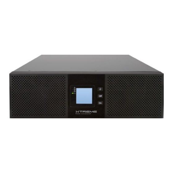
Page 13: Front Panel
SHELF SHIPPED WITH UPS & EBP32 FOR MOUNTING IN A RACK Note: this shelf must be used in order to support the weight of the equipment. Do not install UPS or EBP32 into a rack without using this shelf FRONT PANEL Xtreme Power Conversion Corporation (Rev 3/7/14) Page 13... -
Page 14: Installation Notes
A protection device shall be installed at the distribution panel of the incoming utility power, and should identify the power cables current capacity as well as the overload capacity of the system. Xtreme Power Conversion Corporation (Rev 3/7/14) Page 14... -
Page 15: Power Cables
Protective earth ground cable: connect each cabinet to an earth ground, following the shortest route possible. WARNING! FAILURE TO FOLLOW ADEQUATE GROUNDING PROCEDURES MAY RESULT IN ELECTROMAGNETIC INTERFERENCE OR IN HAZARDS INVOLVING ELECTRICAL SHOCK AND FIRE. Xtreme Power Conversion Corporation (Rev 3/7/14) Page 15... -
Page 16: Power Cables Connection
POWER CABLE CONNECTION DIAGRAM Select the appropriate power cable size, paying attention to the diameter of the connection terminal of the cable, which should be greater than or equal to the connection posts. Xtreme Power Conversion Corporation (Rev 3/7/14) Page 16... - Page 17 INSTALLATION IS OCCURING, ENSURE THAT THE UPS OUTPUT CABLES ARE SAFELY ISOLATED AT THE CABLE ENDS. CAUTION! The earth ground and neutral bonding arrangement must be in accordance with local and/or national electrical code practices. Xtreme Power Conversion Corporation (Rev 3/7/14) Page 17...
-
Page 18: Battery Connection
Factory default settings for the battery quantity is 32 pieces and for a battery capacity of 7AH (charger current = 1A programmable to 6A) Note: Optional 3 party battery configurations of ±192VDC/±204VDC/±216VDC/±240VDC can be used and are available. Xtreme Power Conversion Corporation (Rev 3/7/14) Page 18... - Page 19 (-) TO (-)). DISCONNECT ONE OR MORE BATTERY CELL LINKS IN EACH TIER. DO NOT RECONNECT THESE LINKS AND DO NOT CLOSE THE BATTERY CIRCUIT BREAKER UNLESS ALL CONNECTIONS ARE PROPERLY CHECKED AND APPROVED. UPS -TO- EBP32 BATTERY CONNECTION Xtreme Power Conversion Corporation (Rev 3/7/14) Page 19...
-
Page 20: Ups Multi-Module Installation
UNINTERRUPTIBLE POWER SUPPLY (UPS) UPS Multi-Module Installation The basic installation procedure for a parallel system consisting of two or more R90-20KVA modules is that same as that of a single module. The following provides installation procedures related to a parallel system. -
Page 21: Parallel Cable Installation
The shielded and double insulated control cables must be interconnected in a ring-configuration between UPS modules as shown in the diagram below. The parallel control board is mounted in each UPS module. The ring-configuration ensures high-reliability of the control function. PARALLEL CONNECTION OF UPS Xtreme Power Conversion Corporation (Rev 3/7/14) Page 21... -
Page 22: Remote Emergency Power Off (Epo) For Parallel Systems
UPS in the parallel system is activated, the UPS will send out a remote command and shut down the other UPS’s in the parallel system. CAUTION! The remote emergency kill switch must be voltage-free and “normally open”. EPO CONNECTIONS FOR PARALLEL SYSTEMS Xtreme Power Conversion Corporation (Rev 3/7/14) Page 22... -
Page 23: Requirements For A Parallel System
AC loads. This is to avoid paralleling of unsynchronized AC sources. This interruption is Xtreme Power Conversion Corporation (Rev 3/7/14) Page 23... -
Page 24: Eco Mode
UPS is normal. The UPS then goes to bypass, Utility LED and Bypass LED turn Green, the inverter is now starting. When the inverter is checked “normal”, the UPS goes to Normal Mode and the load is supplied power by the inverter. Xtreme Power Conversion Corporation (Rev 3/7/14) Page 24... -
Page 25: Cold Start Procedure
After the inverter is off, turn the Utility and Battery breakers to “OFF”. The LCD display will extinguish completely and the fan stops spinning in 60 seconds. If there are external battery packs connected, turn the Battery breakers on each battery pack to the “OFF” position. Xtreme Power Conversion Corporation (Rev 3/7/14) Page 25... -
Page 26: Computer Access
• Connect one end of the RS232 communications cable to a computer and the other end to the RS232 port on the UPS • Open the software Muser4000, and choose “system” button Xtreme Power Conversion Corporation (Rev 3/7/14) Page 26... - Page 27 UNINTERRUPTIBLE POWER SUPPLY (UPS) • Choose “Software Parameter Setting” and set selections as shown below and then save settings o COM = COM1 o Baud Rate = 9600 o Protocol = HIP Xtreme Power Conversion Corporation (Rev 3/7/14) Page 27...
- Page 28 On the main page of Muser4000, choose the “Append” button, place the UPS name into “Equipment Name”, and UPS ID address into “Equipment address”. Choose the “Append” button, then the connection between UPS and computer is complete. Xtreme Power Conversion Corporation (Rev 3/7/14) Page 28...
-
Page 29: Parallel Setting
R90 ONLINE USER’S MANUAL UNINTERRUPTIBLE POWER SUPPLY (UPS) Parallel Setting • Connect the UPS with a computer. Power ON the UPS. • Open Muser4000 software and choose “System” > “User Set” Xtreme Power Conversion Corporation (Rev 3/7/14) Page 29... - Page 30 UNINTERRUPTIBLE POWER SUPPLY (UPS) • Select “Set” at “User Set” window CAUTION! When powered by inverter, it is necessary to turn off the inverter before setting the voltage and frequency level in PC Xtreme Power Conversion Corporation (Rev 3/7/14) Page 30...
- Page 31 At the window of “Data Set”, select “Work Mode” with “Parallel” for the Value, then select “Set” as shown in the figure below. If the UPS “beeps” it means the setting is correct. Xtreme Power Conversion Corporation (Rev 3/7/14) Page 31...
- Page 32 (MHTBJHR1CU04 in all UPS to be connected in parallel. If installing 7-10 units in parallel, remove the jumper cap J30/J31 on the control inspection board (MHTBJHR1CU04 in all UPS to be connected in parallel. Xtreme Power Conversion Corporation (Rev 3/7/14) Page 32...
-
Page 33: Communication Port Definitions (Rs232, Rs485)
Monitor UPS alarm information • Monitor UPS running parameters • Timing Off / On setting RS-232 communication data format Baud rate = 9600bps Byte length = 8bit End bit = 2bit Parity check = none Xtreme Power Conversion Corporation (Rev 3/7/14) Page 33... -
Page 34: The Display
Output C (Output L3) Voltage, Frequency & Load Load A Load Load B Load Load C Load Total Load Load Temperature Rectifier / Inverter Temperature CODE Operational status and mode CODE Alarm Code (Warning Message) Xtreme Power Conversion Corporation (Rev 3/7/14) Page 34... - Page 35 If UPS is in single mode, display shows “NOA” or ECO” If UPS is in parallel mode, display shows “PAL” 2. Press SCROLL BUTTON, the UPS goes to the next screen as shown below. PHASE A (L1) INPUT VOLTAGE / FREQUENCY Xtreme Power Conversion Corporation (Rev 3/7/14) Page 35...
- Page 36 R90 ONLINE USER’S MANUAL UNINTERRUPTIBLE POWER SUPPLY (UPS) PHASE B (L2) INPUT VOLTAGE / FREQUENCY PHASE C (L3) INPUT VOLTAGE / FREQUENCY Xtreme Power Conversion Corporation (Rev 3/7/14) Page 36...
- Page 37 R90 ONLINE USER’S MANUAL UNINTERRUPTIBLE POWER SUPPLY (UPS) BAT (POSITIVE) BAT - (NEGATIVE) Xtreme Power Conversion Corporation (Rev 3/7/14) Page 37...
- Page 38 R90 ONLINE USER’S MANUAL UNINTERRUPTIBLE POWER SUPPLY (UPS) PHASE A (L1) OUTPUT VOLTAGE / FREQUENCY PHASE B (L2) OUTPUT VOLTAGE / FREQUENCY Xtreme Power Conversion Corporation (Rev 3/7/14) Page 38...
- Page 39 R90 ONLINE USER’S MANUAL UNINTERRUPTIBLE POWER SUPPLY (UPS) PHASE C (L3) OUTPUT VOLTAGE / FREQUENCY PHASE A (L1) LOAD CAPACITY Xtreme Power Conversion Corporation (Rev 3/7/14) Page 39...
- Page 40 R90 ONLINE USER’S MANUAL UNINTERRUPTIBLE POWER SUPPLY (UPS) PHASE B (L2) LOAD CAPACITY PHASE C (L3) LOAD CAPACITY Xtreme Power Conversion Corporation (Rev 3/7/14) Page 40...
- Page 41 R90 ONLINE USER’S MANUAL UNINTERRUPTIBLE POWER SUPPLY (UPS) TOTAL LOAD CAPACITY INTERNAL TEMPERATURE AND AMBIENT TEMPERATURE Xtreme Power Conversion Corporation (Rev 3/7/14) Page 41...
- Page 42 R90 ONLINE USER’S MANUAL UNINTERRUPTIBLE POWER SUPPLY (UPS) SOFTWARE VERSION & MODEL ALARM CODE Xtreme Power Conversion Corporation (Rev 3/7/14) Page 42...
- Page 43 3. Pressing SCROLL BUTTON, steps through all messages from the first to the last, and then returns back to the first message display. 4. All alarm codes are present when abnormal behaviors occur. Xtreme Power Conversion Corporation (Rev 3/7/14) Page 43...
-
Page 44: Parameters Setting
ECO, PAL, and NOR. Press Off or On to exit the mode setting (save the mode setting), and then goes to output voltage setting or parallel redundancy quantity setting. Xtreme Power Conversion Corporation (Rev 3/7/14) Page 44... -
Page 45: Output Voltage Setting
There are 3 different voltages - 220, 230, 240. Press Off or On to exit the output voltage setting (save the output voltage setting), and then goes to mode setting or frequency setting. Xtreme Power Conversion Corporation (Rev 3/7/14) Page 45... -
Page 46: Frequency Setting
There are 2 different frequencies - 50 or 60 Hz. Press Off or On to exit the frequency setting (save the frequency setting), and then goes to output voltage setting or battery capacity setting. Xtreme Power Conversion Corporation (Rev 3/7/14) Page 46... -
Page 47: Battery Capacity Setting
Enter can adjust battery capacity quickly). Press Off or On to exit the battery capacity setting (save the battery capacity setting), and then goes to frequency setting or battery quantity setting. Xtreme Power Conversion Corporation (Rev 3/7/14) Page 47... -
Page 48: Battery Quantity Setting
Enter button to choose different battery quantity. Battery quantity range is 32, 34, 36, 38, 40. Press Off or On to exit the battery quantity setting (save the battery quantity setting), and then goes to battery capacity setting or bypass voltage upper limit setting. Xtreme Power Conversion Corporation (Rev 3/7/14) Page 48... -
Page 49: Bypass Voltage Upper Limit Setting
5%, 10%, 15%, 25% (25% is only available for 220V output). Press Off or On to exit the bypass voltage upper limit setting (save the bypass voltage upper limit setting), and then goes to battery quantity setting or bypass voltage lower limit setting. Xtreme Power Conversion Corporation (Rev 3/7/14) Page 49... -
Page 50: Bypass Voltage Lower Limit Setting
20%, 30%, 45%. Press Off or On to exit the bypass voltage lower limit setting (save the bypass voltage lower limit setting), and then goes to bypass voltage upper limit setting or parallel ID setting. Xtreme Power Conversion Corporation (Rev 3/7/14) Page 50... -
Page 51: Parallel Id Setting
(MHTBJHR1CU04 in all UPS to be connected in parallel. If installing 7-10 units in parallel, remove the jumper cap J30/J31 on the control inspection board (MHTBJHR1CU04 in all UPS to be connected in parallel. Xtreme Power Conversion Corporation (Rev 3/7/14) Page 51... -
Page 52: Parallel Quantity Setting
(MHTBJHR1CU04 in all UPS to be connected in parallel. If installing 7-10 units in parallel, remove the jumper cap J30/J31 on the control inspection board (MHTBJHR1CU04 in all UPS to be connected in parallel. Xtreme Power Conversion Corporation (Rev 3/7/14) Page 52... -
Page 53: Parallel Redundancy Quantity Setting
(MHTBJHR1CU04 in all UPS to be connected in parallel. If installing 7-10 units in parallel, remove the jumper cap J30/J31 on the control inspection board (MHTBJHR1CU04 in all UPS to be connected in parallel. Xtreme Power Conversion Corporation (Rev 3/7/14) Page 53... -
Page 54: Display Messages
Fault LED on N-Battery Charger fault Continuously Fault LED on DC Bus Over Voltage Continuously Fault LED on DC Bus Below Voltage Continuously Fault LED on DC Bus Unbalance Continuously Fault LED on Xtreme Power Conversion Corporation (Rev 3/7/14) Page 54... -
Page 55: Options
Network Management Card with Environmental Monitor, which is shipped with the SNMP card. SNMP Card: external SNMP optional • Connect the external SNMP adapter to the SNMP port indicated • Tighten the screws Xtreme Power Conversion Corporation (Rev 3/7/14) Page 55... - Page 56 R90 ONLINE USER’S MANUAL UNINTERRUPTIBLE POWER SUPPLY (UPS) The slot called SNMP supports the MEGAtec protocol. We advise NetAgent II-3 port is a tool to remotely monitor and manage any UPS system. EXTERNAL SNMP CARD Xtreme Power Conversion Corporation (Rev 3/7/14) Page 56...
-
Page 57: Troubleshooting
LED is illuminated and the related Contact dealer or distributor code of “Rectifier / Inverter Out of UPS has failed for service and repair Order” or “Output Out of Order” shows in the LCD display Xtreme Power Conversion Corporation (Rev 3/7/14) Page 57... -
Page 58: Batteries
Contact with a grounded battery can result in electrical shock! The likelihood of such shock will be reduced if such grounds are removed during installation and maintenance (applicable to a UPS and a remote battery supply not having a grounded circuit). Xtreme Power Conversion Corporation (Rev 3/7/14) Page 58... -
Page 59: Specifications
Options Maintenance bypass, Output distribution, SNMP Operating Temperature 32 - 104°F (0-40°C) Environment Humidity 0 – 95% non-condensing Altitude 11,500 ft (3500 m) above sea level Approvals CE, EN/IEC 62040-2, EN/IEC 62040-1-1 Xtreme Power Conversion Corporation (Rev 3/7/14) Page 59... -
Page 60: Battery Run Times Using Ebp32
Two or more EBP32 battery packs are recommended for loads over 15kVA/13.5kW. SHIPPING LIST R90-20K UPS Software CD horizontal brackets (front) shelf with mounting hardware manual R90-EBP32 (OPTIONAL horizontal brackets (front) shelf with mounting hardware Xtreme Power Conversion Corporation (Rev 3/7/14) Page 60... -
Page 61: Obtaining Service
3. Mark the RMA number on the outside of all packages. Xtreme Power cannot accept any package without the RMA number marked on the outside of the boxes. -
Page 62: Xtreme Power Conversion Corporation Limited Warranty
XPC Corporation or a XPC Corporation authorized representative before or after delivery with regard to the use or application of Xtreme Power Conversion equipment is furnished on the basis that it represents XPC Corporations best judgment under the situation and circumstances, but it is used at the recipient’s sole risk.
Need help?
Do you have a question about the 20kVA and is the answer not in the manual?
Questions and answers