
Related Manuals for Xtreme M90-80 Series


Summary of Contents for Xtreme M90-80 Series
- Page 1 M90-80 & 140 Modular Online Three-Phase UPS 15-140kVA Models User & Installation Manual www.xpcc.com | © 2019 Xtreme Power Conversion Corporation. All rights reserved. (Rev 9/23/19)
-
Page 2: Table Of Contents
2.12 Battery Module Installation....................23 3. Operation Mode and UPS Operation............26 3.1 Block Diagram of UPS......................26 3.2 Operation Mode........................27 3.3 UPS Operation..........................30 4. Control Panel and Display Description.............40 4.1 Introduction..........................40 4.2 Screen Description........................41 4.3 Alarm List..........................62 Xtreme Power Conversion Corporation Page 2... - Page 3 7.1 Replacement Procedures Of Power Module................71 7.2 Replacement Procedures Of STS Module................71 7.3 Replacement Procedures Of Battery Module................71 7.4 Replacement Procedures Of Air Filter..................71 8. Specifications..................72 9. Obtaining Service..................74 10. Xtreme Power Conversion Limited Warranty.........75 Xtreme Power Conversion Corporation Page 3...
-
Page 4: Safety
- four poles for three phases. 1.4 Maintenance • Only qualified service personnel should perform the battery installation. • The following PRECAUTIONS should be observed: 1. Remove watches, rings, or other metal objects. Xtreme Power Conversion Corporation Page 4... -
Page 5: Recycling The Used Battery
Lead Acid battery life is reduced above 25°C (77F). 6. If necessary, install a system of room extractor fans to avoid formation of room temperature. Air filters are necessary if the UPS is operated in a dusty environment. Xtreme Power Conversion Corporation Page 5... -
Page 6: Unpacking
1. Use a forklift to move the product to installed area. Please make sure the bearing capacity of forklift is suf- ficient. 2. Please follow the order in the figures below to remove carton and foams. Figure 2-1 Figure 2-2 Xtreme Power Conversion Corporation Page 6... - Page 7 4. Remove 4 fixing cabinet plates and loosen leveling feet by rotating them counterclockwise. Then, move the cabinet from the pallet. Refer to Figure 2-4. 5. To fix the cabinet in position, simply rotate leveling feet clockwise. Refer to Figure 2-5. Figure 2-4 Figure 2-5 Xtreme Power Conversion Corporation Page 7...
-
Page 8: Moving The Cabinet
5. At the bottom of the UPS, the four casters help you to move the UPS to a designated area. Before you move the UPS, please turn the four leveling feet counterclockwise to raise them off the ground. This protects the leveling feet from damage when moving the UPS. Refer to Figure 2-6. Figure 2-6 Xtreme Power Conversion Corporation Page 8... -
Page 9: Types Of Ups Cabinet
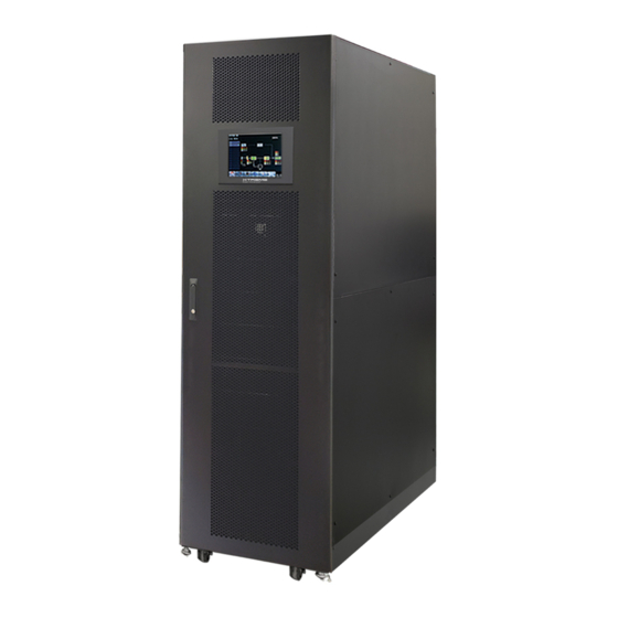
Inside the cabinet, there are Breakers, STS Module, Power Module slots and Battery module slots (Battery Module Slots is only for M90-80). All wiring terminal blocks are located in the back of cabinet. Internal Battery Module Slots are only for M90-80 Xtreme Power Conversion Corporation Page 9... - Page 10 M90 User’s Manual Uninterruptible Power Supply Figure 2-7 Exterior Mechanical Data Dimensions UPS cabinet Width Depth Height 23.6” 43.3” 79.1” Figure 2-8 Dimensions Xtreme Power Conversion Corporation Page 10...
- Page 11 (Q3), STS Module, Power Module slots and Battery Module slots (Battery Module Slots is only for M90-80). M90-80 M90-140 1. Battery Breaker 2. STS Module 3. Power Module 4. Battery Module Figure 2-9 Front View Xtreme Power Conversion Corporation Page 11...
-
Page 12: Internal Mechanisms
After opening the front door, there are three breakers, Main Breaker (Q1), Maintenance Breaker (Q2) and Output Breaker (Q3). For the M90-80, there is a battery breaker for internal battery modules. You can see it when you open the rear door. Xtreme Power Conversion Corporation Page 12... - Page 13 M90 User’s Manual Uninterruptible Power Supply M90-80 M90-140 Figure 2-11 Front Breakers Battery Breaker M90-80 Figure 2-12 Rear Breaker Xtreme Power Conversion Corporation Page 13...
- Page 14 Includes R, S, T and Neutral terminals. For UPS Grounding For UPS grounding Includes one grounding terminal. Includes: Positive (+), Negative (-) and Battery Input Block Connects an external battery cabinet Neutral (N) terminals. Figure 2-14 M90-80 Terminal Blocks Xtreme Power Conversion Corporation Page 14...
-
Page 15: Control Panel
Through the graphic LCD display, the user can easily understand the operation mode of UPS. In addition, the mea- surement, parameters, versions of firmware and warnings can be browsed in the friendly interface. For detailed information, please refer to Charter 4. Figure 2-16 Control Panel Xtreme Power Conversion Corporation Page 15... -
Page 16: Introduction Of Modules
The number of Power Modules installed in the UPS can be based on the initial needs. Once the power requirement increases, you can easily install more Power Modules without interrupting the operation of the system. Battery Breaker Figure 2-17 Front View of Module Xtreme Power Conversion Corporation Page 16... - Page 17 Local communication interface. SNMP Slot This slot can work with optional cards, SNMP, AS400 or Modbus card. Dry contact CN1 ~ CN8. For detailed information, please refer to Chapter 5. ports Figure 2-18 STS Module Xtreme Power Conversion Corporation Page 17...
- Page 18 ON/OFF 0.15 sec The CAN Bus communication doesn’t work. Figure 2-19 M90-PWRM DIP switch setting and Module Address Module Address DIP SWITCH Module Address DIP SWITCH Table 2-1 DIP switch setting and Module Address Xtreme Power Conversion Corporation Page 18...
- Page 19 The SW1 and SW2 position have been well installed before leaving factory. It’s not necessary to change it for single UPS system application. Module ID Assignment SW1 & SW2 Module Address Module ID SW1 & SW2 Module Address Module ID Table 2-2 Module ID Assignment Xtreme Power Conversion Corporation Page 19...
-
Page 20: Power Cable
2.10.1 AC input and output maximum current and power cable configuration. For M90-80 models Model 15KVA 20KVA 30KVA 40KVA 45KVA 60KVA 75KVA 80KVA Current (A) 60.1 120.2 180.3 240.4 Power cable (mm2) Fixation torque force (lb-in) 88.3 88.3 88.3 88.3 88.3 88.3 88.3 88.3 Xtreme Power Conversion Corporation Page 20... - Page 21 Fixation torque force (lb-in) Model 80KVA 90KVA 100KVA 105KVA 120KVA 140KVA Current (A) 514.5 Power cable (mm2) 120 x 2 120 x 2 150 x 2 150 x 2 185 x 2 Fixation torque force (lb-in) Xtreme Power Conversion Corporation Page 21...
-
Page 22: Wiring
The N must be connected firmly. A warning message will be indicated, if the N is not connected well. There is no Breaker between Input2 and STS Module, the STS module is waked up when Input2 is powered, though the Q1 Breaker is OFF. Xtreme Power Conversion Corporation Page 22... -
Page 23: Power Module Installation
1. Adjust the DIP switch positions to set the different Module Address. Refer to Table 2-1. 2. Place the ready switch at the front panel of the module to the “ ” position (i.e., in unready state). 3. Insert the Power Module into an unoccupied slot by two persons. Xtreme Power Conversion Corporation Page 23... - Page 24 Uninterruptible Power Supply 4. Secure the Power Module to the cabinet by fixing the screws at the front panel of the Power Module. 5. Move the ready switch to the “ ”position (i.e., in ready state). Xtreme Power Conversion Corporation Page 24...
- Page 25 1. Open the UPS’s front door and remove the panel of battery module slot. 2. There are 4 rails for inserting the Battery Modules in the same layer. Four Battery Modules MUST be installed to form a set of Battery. Xtreme Power Conversion Corporation Page 25...
-
Page 26: Operation Mode And Ups Operation
4. Secure the Battery Module to the cabinet by fixing the screws of the Battery Module. 3. Operation Mode and UPS Operation 3.1 Block Diagram of UPS Figure 3-1: Wiring diagram for dual inputs Xtreme Power Conversion Corporation Page 26... -
Page 27: Operation Mode
Upon connecting to utility input power, the UPS is in Standby mode before UPS is turned on (if BYPASS enable set- ting is Disabled), and charger function will be active when the battery is present. The load is not powered under this mode. Figure 3-3 : Standby Mode Diagram Xtreme Power Conversion Corporation Page 27... - Page 28 If the transference is caused by a recoverable reason, the UPS will turn back to line mode when abnormal situation is solved. Xtreme Power Conversion Corporation Page 28...
- Page 29 Or when the UPS has discharged the battery to the cut-off level, the UPS will enter into shutdown mode as well. When the UPS enters this mode, it is going to shut off the control power of UPS. The rectifier, charger and inverter are all in off state. Xtreme Power Conversion Corporation Page 29...
-
Page 30: Ups Operation
Make sure the ready switch on the Power Module has been moved to the “Locked” position. • Make sure all the breakers are switch OFF. 3.3.1 AC Startup Ensure to follow this procedure when turning on the UPS from a fully powered-down condition. Xtreme Power Conversion Corporation Page 30... - Page 31 Step 4: Switch ON the input breaker (Q1). The UPS will enter into Standby Mode, if the setting of Bypass mode is disabled. Or the UPS will enter into Bypass Mode, if the setting of Bypass mode is enabled. Xtreme Power Conversion Corporation Page 31...
- Page 32 Step 6: Press Power ON/OFF button for two seconds to enter into Line Mode as shown below. After turned on, UPS will do self-test and start Inveter up. UPS will be transferred to Line mode when all power modules are ready. Xtreme Power Conversion Corporation Page 32...
- Page 33 Step 2: Press the “Battery Start” button on any one of Power Modules to start up the control power of all Power modules and STS as shown below. Battery Start Button Step 3: After pressing the “Battery Start” button, UPS will enter into Standby mode. Refer to the diagram below for LCD display. Xtreme Power Conversion Corporation Page 33...
- Page 34 Follow the instruction to transfer to Maintenance Bypass and UPS protection as below. 3.3.3.1 Transfer to maintenance bypass Step 1: Remove the mechanical lock plate of Maintenance Bypass Breaker. Step 2: Make sure the UPS operates in Bypass mode as shown below. Xtreme Power Conversion Corporation Page 34...
- Page 35 Step 3: Please enter LCD SETUP MENU and choose “SYSTEM” to ensure that the “Bypass mode” is enabled. If the “Bypass mode” is disabled, you have to set it enabled. Then, exit the SETUP menu and check if the UPS operates in bypass mode. Xtreme Power Conversion Corporation Page 35...
- Page 36 3.3.4.1 Bypass Mode/ Standby Mode Turn Off Operation When the UPS neither is turned on nor turned off, the UPS operates in the Standby Mode or Bypass Mode. It de- pends on the “Bypass Mode” Setting. Xtreme Power Conversion Corporation Page 36...
- Page 37 Step 1: Switch OFF the Main Breaker. The LCD diagrams are shown below. Bypass Mode Setting is Disabled UPS enters Shutdown Mode. It is normal the Un-Connection is shown when Power Modules have shut off their control power. Xtreme Power Conversion Corporation Page 37...
- Page 38 The LCD diagrams are shown below when the UPS operates in the Line Mode. Press “Power On/Off” button for 2 seconds to turn off the UPS. Or use the Menu-Control-System Turn Off to turn off the UPS. Xtreme Power Conversion Corporation Page 38...
- Page 39 Press “Power On/Off” button for 2 seconds to turn off the UPS. Or use the Menu-Control-System Turn Off to turn off the UPS. After turning off, the UPS will tranfer to Standby Mode. Next, follow the Bypass Mode/ Standby Mode Turn Off Operation procedure. Xtreme Power Conversion Corporation Page 39...
-
Page 40: Control Panel And Display Description
There is power output for the load. LOAD Green There is no power output for the load. Load on inverters. INVERTER Green Inverters not operating. Load on Battery. BATTERY Flashing Low battery Battery converter is normal and battery is charging. Xtreme Power Conversion Corporation Page 40... -
Page 41: Screen Description
Upon starting, the UPS executes self-test. The initial screen displays and remains still in approximately 5 seconds as shown in Figure 4-2. Figure 4-2 Initial screen 4.2.2 Main Screen After initialization, the main screen will display as Figure 4-3. Main screen is divided into six parts. Xtreme Power Conversion Corporation Page 41... - Page 42 Power module fault Power module is operated normally. (3) Main Menu: Touch icon to enter sub screen. (4) UPS Flow Chart: Current flow chart and measurement data. (5) UPS power rating. (6) Date and Time. Xtreme Power Conversion Corporation Page 42...
- Page 43 M90 User’s Manual Uninterruptible Power Supply 4.2.3 Control Screen Touch icon to enter into the sub-menu as shown in Figure 4-5 and 4-6. Figure 4-5 Control menu tree Figure 4-6 Control screen page Xtreme Power Conversion Corporation Page 43...
- Page 44 Input, Output, Bypass, Load or Battery to monitor detailed status under “System” or “Module” direc- tory. Please refer all screens in Figure 4-8 and 4-9. All detailed measurement items are listed in Table 4-4. Figure 4-8 Measurement menu Xtreme Power Conversion Corporation Page 44...
- Page 45 M90 User’s Manual Uninterruptible Power Supply Figure 4-9 System Measurement Screens Touch icon to monitor module measurement value. Xtreme Power Conversion Corporation Page 45...
- Page 46 Battery run time remaining. Units 1sec. Capacity (%) The percentage of the capacity of the battery. Units 1%. Test Result Battery test result Charging Status Battery charging status Temperature1(°) Battery cabinet temperature of STS module. Units 0.1°. Xtreme Power Conversion Corporation Page 46...
- Page 47 Setting item Test verter Main- Mode Mode Mode Mode Mode Mode User Mode Mode tainer Model Name Language TIME Change Password Baud Rate General Audible Alarm Factory Reset EEPROM Reset EPO Function Save Setting Xtreme Power Conversion Corporation Page 47...
- Page 48 Step 2: Select modified item and it will show current value and setting in the screen. Simply choose current setting and it will list all alternatives. Please choose the modified setting. Step 3: Choose icon to confirm the setting change or choose icon to cancel the setting. Figure 4-13 Setting procedure Xtreme Power Conversion Corporation Page 48...
- Page 49 MUST be set after UPS installation Set New Password. Change Password 0000 (Default) Set COM Port0 Baud Rate • 2400 (Default) • 4800 • 9600 Baud Rate Set COM Port1 Baud Rate • 2400 (Default) • 4800 • 9600 Xtreme Power Conversion Corporation Page 49...
- Page 50 EPO Function Save Setting Output Voltage Bypass Voltage Range Bypass Frequency Range Converter Mode ECO Mode Bypass Mode System Auto-Restart Cold Start Battery Mode Delay Time System Shutdown Time System Restore Time Redundancy Charger Test Xtreme Power Conversion Corporation Page 50...
- Page 51 UPS is operated in certain mode. Please check setting item availability table 4-5 for the details. If it’s not set up under specific mode, the warning screen will appear. Refer to figure 4-16. Figure 4-15 Setup-System screen Xtreme Power Conversion Corporation Page 51...
- Page 52 • Disable (Default) • Enable Set bypass mode • Disable (Default) Bypass Mode • Enable MUST be reviewed after UPS installation. If you need the Bypass power when UPS is OFF, please enable it. Xtreme Power Conversion Corporation Page 52...
- Page 53 The Setup-Battery screen and setting list as shown in Figure 4-17 and table 4-9. Battery setting can be set only when UPS is operated in standby mode. If it’s not in standby mode, the warning screen will appear as shown in Figure 4-16. Xtreme Power Conversion Corporation Page 53...
- Page 54 Set battery low capacity (20~50%) Battery Low Capacity Shutdown SETTING • 20% (Default) Set battery voltage point for system shutdown Battery Shutdown Voltage in battery mode (10.0~11V) x (battery Number) • 10V x Battery Number (Default) Xtreme Power Conversion Corporation Page 54...
- Page 55 The Setup-Pre-Alarm screen and setting list as shown in Figure 4-18 and table 4-9. Pre-Alarm setting can be set in any operation mode. Figure 4-18 Setup-Pre-Alarm screen Pre-Alarm setting can be set in any operation mode. See Setup-Pre-Alarm setting list in Table 4-10. Xtreme Power Conversion Corporation Page 55...
- Page 56 There are three sub-menus, Identification, System and Battery. Figure 4-19 Information menu 4.2.7.1 INFORMATION - Identification Screen When Identification submenu is clicked, the Model Name, Serial No. and Firmware Version will be displayed, as shown in Figure 4-20. Xtreme Power Conversion Corporation Page 56...
- Page 57 When System submenu tab is touched, the system power, nominal voltage, nominal frequency … etc. informa- tion will be displayed, as shown in Figure 4-21 and 4-22. Touch UP and DOWN arrows to switch different pages. Figure 4-21 INFORMATION System screen page 1 Xtreme Power Conversion Corporation Page 57...
- Page 58 When event occurs, you will see flashing icon in the Main Screen as shown in Figure 4-24. You also can touch icon to check the latest event lists, history events and reset all events as shown in Figure 4-25. Xtreme Power Conversion Corporation Page 58...
- Page 59 When event occurs, it will display Module ID and alarm code in Current Events screen. It can save up to 50 events in current list. Only 10 events can be listed in one page. Therefore, if it exceeds more than 10, you have to press icon to read other event as shown in Figure 4-26. Xtreme Power Conversion Corporation Page 59...
- Page 60 Module ID. (Refer to Table 4-12 Alarm List) In order to record more historical information about the UPS system, the important setting changed (refer to Table 4-13 Important setting changed), UPS opera- Xtreme Power Conversion Corporation Page 60...
- Page 61 The Maintainer password is required to enter Reset All Events screen as shown in Figure 4-28. After entering cor- rect password, it will pop up reconfirmed screen. Then, touch icon to reset all events or touch icon to cancel this action as shown in Figure 4-29. Figure 4-28 Reset All Events screen Xtreme Power Conversion Corporation Page 61...
-
Page 62: Alarm List
S phase inverter Output Negative Power over range Fault! Inverter T Negative Power T phase inverter Output Negative Power over range Fault! Over Load Fault Heavy overload causes UPS fault. Fault! Battery Fault Batteries reversed Xtreme Power Conversion Corporation Page 62... - Page 63 Warning! Parallel Rack Config. Wrong Parallel Rack Configure error Warning! Parallel Firmware Error Power module parallel firmware error Warning! Battery Voltage Low Battery voltage is too low. Warning! ID Conflict Power module ID conflict. Pre-Alarm! Line Voltage Fail Line voltage over range Xtreme Power Conversion Corporation Page 63...
-
Page 64: History Record
UPS Mode! Bypass Mode UPS Mode! Line Mode UPS Mode! Battery Mode UPS Mode! Battery Test Mode UPS Mode! Fault Mode UPS Mode! Converter Mode UPS Mode! ECO Mode UPS Mode! Shutdown Mode UPS Mode! Un-Connection Xtreme Power Conversion Corporation Page 64... -
Page 65: Interface And Communication
The Emergency Power off (EPO) Function in UPS can be operated by an assigned remote contact. Users can set the logic (N.C or N.O) of this EPO Function through LCD panel. X1 is the remote EPO input port. The port is shown in Figure 5-2 and described in Table 5-1. Xtreme Power Conversion Corporation Page 65... - Page 66 Table 5-2: Description of Maintenance Bypass Switch State port Name Position Description Maintain Bypass Pin1 X4.1 Maintenance bypass switch state Maintain Bypass Pin 2 X4.2 Maintenance bypass switch state X4.3 No use X4.4 No use Xtreme Power Conversion Corporation Page 66...
-
Page 67: Extra Comm. Slot
5.3 Local Communication Ports – RS232 & USB Note: The RS232 and USB ports can’t work simultaneously. 5.4 SNMP Slot The SNMP card or AS400 card can be inserted into this slot to work with the UPS. Xtreme Power Conversion Corporation Page 67... -
Page 68: Troubleshooting
Or contact service personnel. fan is working Fault! CAN Fault CAN communication fault Contact service personnel. Synchronized trigger signal Fault! TRIG0 Fault Contact service personnel. fault Fault! Relay Fault Inverter relay fault Contact service personnel. Xtreme Power Conversion Corporation Page 68... - Page 69 Warning! Internal Initial Fail As stated. Contact service personnel. Warning! Comm. Syn. Signal Communicate Synchronization Contact service personnel. Fail Signal Fail Communicate Trigger signal Warning! Comm. TRIG0 Fail Contact service personnel. fault Xtreme Power Conversion Corporation Page 69...
-
Page 70: Service
6. Push the module into the cabinet and tighten the screws on both sides. If there are more than one power modules to re-install, please wait 30-second before installing another module. 7. The re-installed Power Module will be turned on automatically when UPS is in line mode. Xtreme Power Conversion Corporation Page 70... -
Page 71: Replacement Procedures Of Power Module
1. Open the front door of the UPS and the air filters are on the back of the door. 2. Remove a fixing bar on either side of the air filter. 3. Remove the air filter, and insert a clean one. 4. Replace the fixing bar. Xtreme Power Conversion Corporation Page 71... -
Page 72: Specifications
External maintenance bypass, 480V input transformer, output distribution, AVAILABLE OPTIONS battery temperature sensor, 15kVA power modules *Depending on load level **Battery life is reduced above 30°C, UPS capacity derates above 30°C and 5,200 ft above sea level Xtreme Power Conversion Corporation Page 72... - Page 73 AVAILABLE OPTIONS External maintenance bypass, 480V input transformer, output distribution, battery temperature sensor *Depending on load level **Battery life is reduced above 30°C, UPS capacity derates above 30°C and 5,200 ft above sea level Xtreme Power Conversion Corporation Page 73...
-
Page 74: Obtaining Service
2. Verify there are no circuit breakers tripped. 3. Call your dealer for assistance. If you cannot reach your dealer, or if they cannot resolve the problem, call Xtreme Power Conversion Corp Technical Support at 800.582.4524. Technical support inquiries can also be made at support@xpcc.com. -
Page 75: Xtreme Power Conversion Limited Warranty
Any technical advice furnished by XPC Corporation or a XPC Corpora- tion authorized representative before or after delivery with regard to the use or application of Xtreme Power Con- version equipment is furnished on the basis that it represents XPC Corporations best judgment under the situation and circumstances, but it is used at the recipient’s sole risk.
Need help?
Do you have a question about the M90-80 Series and is the answer not in the manual?
Questions and answers