Xtreme NXRTi 1000VA User & Installation Manual
Online ups
Hide thumbs
Also See for NXRTi 1000VA:
- User & installation manual (47 pages) ,
- User & installation manual (25 pages) ,
- User & installation manual (27 pages)

Related Manuals for Xtreme NXRTi 1000VA


Summary of Contents for Xtreme NXRTi 1000VA
- Page 1 NXRTi Online UPS 1000VA, 2000VA, 3000VA Models User & Installation Manual www.xpcc.com | © 2015 Xtreme Power Conversion Corporation. All rights reserved. (Rev 6/23/15)
-
Page 2: Table Of Contents
Turning Off the UPS When in Utility Mode..................20 Turning Off the UPS When in Battery Mode..................20 Self Test & Mute Test Operation....................20 Parameter Setting..........................21 ECO Mode Setting..........................21 Bypass Output Setting........................22 Parameter Inquiring........................23 Run Mode............................. 25 Xtreme Power Conversion Corporation Page 2... - Page 3 Troubleshooting..................27 LED Indication and Warning Table....................28 Specifications.....................30 Shipping List....................30 Obtaining Service..................31 Xtreme Power Conversion Limited Warranty..........32 Appendix A: Extended Battery Pack User Guide.........33 Estimated Run Time for UPS with Extended Battery Packs............33 LED Description..........................35 Extended Battery Pack Operation....................35 Extended Battery Pack Installation....................36 Extended Battery Pack Q &...
- Page 4 The instructions contained within this safety manual are deemed important and should be closely followed at all times during installation and follow-up maintenance of the UPS and batteries. Xtreme Power Conversion Corporation Page 4...
-
Page 5: Special Symbols
EMC standard/Safety standard Our products are manufactured in accordance with the following EMC international grade standards and has passed the CE authentication: EMC standard number Safety standard number IEC62040-2 IEC62040-1 IEC61000-4-2 GB4943-2005 IEC61000-4-3 IEC61000-4-4 IEC61000-4-5 Xtreme Power Conversion Corporation Page 5... -
Page 6: Introduction
• DC power is converted to AC in the inverter, passing it on to the load. • Power is maintained from the battery during a power failure. • The converter increases voltage appropriately for the inverter. Xtreme Power Conversion Corporation Page 6... -
Page 7: Functions And Characteristics
» NXRTi-EBP1 for 1000 » NXRTi-EBP2 for 2000 » NXRTi-EBP3 for 3000 τ Connectivity Options –SNMP/WEB card τ Xtreme Power Distribution Units (XPDU) See the Specification section of this manual for additional model information. Xtreme Power Conversion Corporation Page 7... - Page 8 NXRTi User’s Manual Uninterruptible Power Supply NXRTi front view NXRTi-1000 rear view NXRTi-2000 and NXRTi-3000 rear view Xtreme Power Conversion Corporation Page 8...
-
Page 9: Led Description
If this INVERTER LED is illuminated it indicates that everything is normal and the UPS is being powered by incoming AC utility or by the batteries. After starting the UPS, the four LED’s will light and go out one-by-one, cycling until the UPS starts successfully. Xtreme Power Conversion Corporation Page 9... -
Page 10: Lcd Descriptions
This section displays the capacity of the battery and amount of load on the UPS output. Each pane represents 20% capacity. When the capacity of the battery is 80-100% 5 panes would be displayed. When the load reaches 40-60% Xtreme Power Conversion Corporation Page 10... - Page 11 When the UPS is in Battery Mode, the number of icons for the charger status section will vary according to the changeable capacity of the battery. For example, there are five panes in the figure below, so the corresponding number of icons is five rows. Xtreme Power Conversion Corporation Page 11...
-
Page 12: Rs-232 Standard Interface
Note: Many factors can affect the amount of power that your computer system will require. The total load that you will be placing on the battery-powered outlets should not exceed 85% of the UPS capacity. Xtreme Power Conversion Corporation Page 12... -
Page 13: Hardware Installation Guide
Space and ventilation requirements must be met. Ensure there is 100mm behind and 50mm on the sides of the UPS for proper ventilation. • Ensure that the front of the UPS remains clear for user operation. Xtreme Power Conversion Corporation Page 13... -
Page 14: Installation
Two plastic base brackets interconnect and flatten for holding 2U base unit configuration. The same plastic base assembly plus a 1U plastic base extension bracket are connected together as shown below to accommodate 3U enclosures. Xtreme Power Conversion Corporation Page 14... - Page 15 NXRTi User’s Manual Uninterruptible Power Supply Xtreme Power Conversion Corporation Page 15...
-
Page 16: 19" Cabinet Ear Installation
NXRTi User’s Manual Uninterruptible Power Supply 19” Cabinet Ear Installation The bracket is installed on the UPS as shown below UPS Front Corner UPS Rack Bracket UPS Front Corner With Bracket Installed Xtreme Power Conversion Corporation Page 16... - Page 17 NXRTi User’s Manual Uninterruptible Power Supply Tower Assembled Unit Rack Assembled Unit Xtreme Power Conversion Corporation Page 17...
-
Page 18: Initial Connection And Startup
6 hours before use. 5. Start and configure the UPS Front Panel Buttons • ON/OFF BUTTON Press and hold button(s) for more than ½ second to turn on or turn off the UPS Xtreme Power Conversion Corporation Page 18... - Page 19 Highlight and click “Configure” to change the network settings on the NetAgent discovered. • Disconnect the cable to the PC and connect the SNMP card to your network. • Access the SNMP card via the network and make configuration changes using the manual downloaded previously. Xtreme Power Conversion Corporation Page 19...
-
Page 20: User's Operations
When the UPS is in on-line mode, Press and Hold the Self-Test / Mute Button for more than 1 second, the LED lights and go out in order. The UPS arrives then at its Self-Test Mode and tests its status. The UPS will Xtreme Power Conversion Corporation Page 20... -
Page 21: Parameter Setting
The “ON” below the ECO will flash. Press and hold the inquiring button for more than ½ second but less than 2 seconds to determine whether the ECO function is used or not. If used, the corresponding word is “ON”, if not, the word is “OFF”. Xtreme Power Conversion Corporation Page 21... -
Page 22: Bypass Output Setting
2 seconds, exit from the setting interface and return to the main interface. • After setting bPS as ON, when utility power is plugged in without turning on the UPS, or no utility power is Xtreme Power Conversion Corporation Page 22... -
Page 23: Parameter Inquiring
WATT and VA. Temperature: Display the temperature of the inverter in the UPS. The graphics shows the temperature of the in- verter is 37°C. Xtreme Power Conversion Corporation Page 23... - Page 24 Battery: Display the voltage and capacity of the battery (determined by type). The graphic shows the battery volt- age is 28v, the capacity of battery is 100% (the capacity of battery is an approximation). Xtreme Power Conversion Corporation Page 24...
-
Page 25: Run Mode
20 hours depending on the battery volume and the load. If battery discharge for 20 hours and the load is lower than 10% of rated power, the UPS will alarm for ½ hour and then shutdown to protect the batteries. Xtreme Power Conversion Corporation Page 25... - Page 26 UPS. After UPS turned on, please connect load one-by-one. • It is recommended that the generator capacity is twice the UPS rated capacity. • Do not use the ECO mode when the quality of the input AC utility is not stable. Xtreme Power Conversion Corporation Page 26...
-
Page 27: Maintenance
3. If you need help, contact our service department, the following messages should be provided for analysis: • UPS MODEL NO. and SERIAL NO. • Date of fault happened • Detailed description of the problem (include indicator statements from front panel) Xtreme Power Conversion Corporation Page 27... -
Page 28: Led Indication And Warning Table
Affirm if the battery switch is closed four seconds Once every Inverting mode Affirm if the battery switch is closed four seconds Power up or start Six times Affirm if the battery is connected well Output overload protection Xtreme Power Conversion Corporation Page 28... - Page 29 Fault occurs inside UPS Contact supplier for servicing The icon of charger status on Charger doesn’t work nor- Contact supplier for servicing LCD display flashes and buzzer mally or battery aged beeps once per second Xtreme Power Conversion Corporation Page 29...
-
Page 30: Specifications
Shipping List 1. (1) UPS 2. (1) User’s and Installation Manual 3. (1) 6 ft RS232 cable 4. (1) UPSILON CD (monitoring software) 5. (2) sets of mounting brackets 6. (1) input power cord Xtreme Power Conversion Corporation Page 30... -
Page 31: Obtaining Service
2. Verify there are no circuit breakers tripped. 3. Call your dealer for assistance. If you cannot reach your dealer, or if they cannot resolve the problem, call Xtreme Power Conversion Corp Technical Support at 800.582.4524. Technical support inquiries can also be made at support@xpcc.com. -
Page 32: Xtreme Power Conversion Limited Warranty
Any technical advice furnished by XPC Corporation or a XPC Corpora- tion authorized representative before or after delivery with regard to the use or application of Xtreme Power Con- version equipment is furnished on the basis that it represents XPC Corporations best judgment under the situation and circumstances, but it is used at the recipient’s sole risk. -
Page 33: Appendix A: Extended Battery Pack User Guide
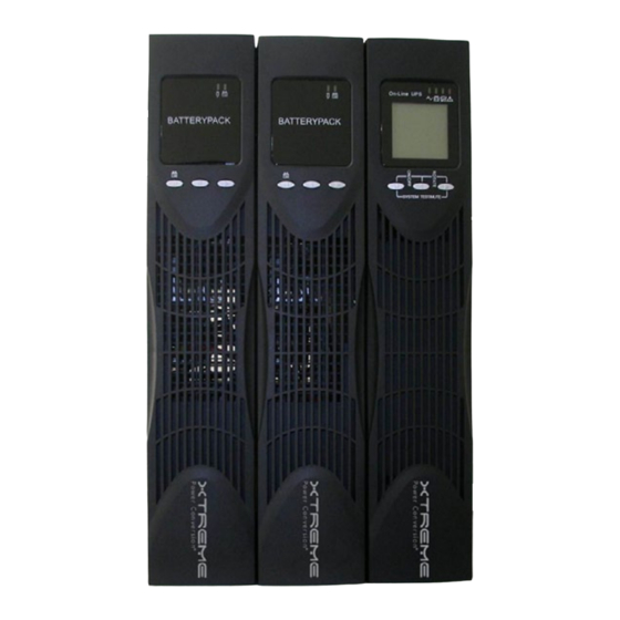
EBP’s AND MAKE SURE YOU ONLY CONNECT THE EBP TO LIKE EBP’s OR UPS INDICATED ABOVE. DC VOLTAGES ARE MARKED ON BOTH THE UPS AND THE EBP – MAKE SURE THEY MATCH. Caution Label on EBP Cable Connectors - Please Check Voltages Carefully NXRTi-EBP1 rear view Xtreme Power Conversion Corporation Page 33... - Page 34 NXRTi User’s Manual Uninterruptible Power Supply NXRTi-EBP2 rear view NXRTi-EBP3 rear view NXRTi-1000 with (2) NXRTi-EBP1 Xtreme Power Conversion Corporation Page 34...
-
Page 35: Led Description
1. The DC Circuit Breaker on the rear of the EBP connects and disconnects the DC bus voltage from the EBP to the UPS. The DC Circuit Breaker will also trip to the OFF position in the event of an over-current condition in the EBP. Xtreme Power Conversion Corporation Page 35... -
Page 36: Extended Battery Pack Installation
(2 each per connector end). 6. Repeat the above procedure for testing and securing each additional EBP required. CAUTION: Do not use extension cords when connecting input AC power to UPS or EBP’s. Xtreme Power Conversion Corporation Page 36... -
Page 37: Extended Battery Pack Q & A
The charger on each EBP functions independently from the others. One EBP charger may be charging while another one might be at 100% and the charger turned off. This is normal operation of the EBP. Xtreme Power Conversion Corporation Page 37...
Need help?
Do you have a question about the NXRTi 1000VA and is the answer not in the manual?
Questions and answers