Xtreme NXRTi 1000VA User & Installation Manual
Online ups
Hide thumbs
Also See for NXRTi 1000VA:
- User & installation manual (43 pages) ,
- User & installation manual (13 pages) ,
- User & installation manual (14 pages)

Related Manuals for Xtreme NXRTi 1000VA


Summary of Contents for Xtreme NXRTi 1000VA
- Page 1 UNINTERRUPTIBLE POWER SUPPLY (UPS) NXRTi Online UPS 1000VA, 2000VA, 3000VA Models USER & INSTALLATION MANUAL www.xpcc.com | © 2013 Xtreme Power Conversion Corporation. All rights reserved.
-
Page 2: Table Of Contents
Turning Off the UPS when in Utility Mode ..................... 23 Turning Off the UPS when in Battery Mode ................... 23 Self Test & Mute Test Operation ......................23 Parameter Setting ........................... 24 ECO mode setting..........................24 Xtreme Power Conversion Corporation (Rev 8/29/13) Page 2... -
Page 3: Xtreme Power Conversion Corporation (Rev 8/29/13 Page
Estimated Run Time for UPS with Extended Battery Packs ..............40 LED Description ............................43 Extended Battery Pack Operation ......................43 Extended Battery Pack Installation ......................45 Extended Battery Pack Q & A ........................45 Xtreme Power Conversion Corporation (Rev 8/29/13) Page 3... -
Page 4: Important Safety Instructions
A battery can present a risk of electric shock and high short circuit current. The following precaution should be observed when working on batteries: • Remove watches, rings or other metal objects. • Use tools with insulated handles. Xtreme Power Conversion Corporation (Rev 8/29/13) Page 4... -
Page 5: Special Symbols
Before conducting any maintenance, repair, or shipment, first ensure that everything is turned off completely and disconnected. For additional safety instructions, please use the Safety Manual as a reference. Special Symbols The following symbols used on the UPS warn you of precautions: Xtreme Power Conversion Corporation (Rev 8/29/13) Page 5... -
Page 6: Introduction
PRODUCT DESCRIPTION Many different kinds of sensitive electrical equipment can be protected by an Uninterruptible Power Supply (UPS) including computers, workstations, process control systems, telecommunications systems, Xtreme Power Conversion Corporation (Rev 8/29/13) Page 6... -
Page 7: Double Conversion On-Line Technology
DC power is converted to AC in the inverter, passing it on to the load. • Power is maintained from the battery during a power failure. • The converter increases voltage appropriately for the inverter. Xtreme Power Conversion Corporation (Rev 8/29/13) Page 7... -
Page 8: Functions And Characteristics
ECO Function can help to save electricity by allowing the UPS to operate in a line-interactive mode. The load is supplied with utility power directly while the inverter is in a standby mode until needed. Xtreme Power Conversion Corporation (Rev 8/29/13) Page 8... -
Page 9: System Configuration
NXRTi-EBP2 for 2000 NXRTi-EBP3 for 3000 o Connectivity Options –SNMP/WEB card o Xtreme Power Distribution Units (XPDU) See the Specification section of this manual for additional model information. NXRTi-series FRONT VIEW NXRTi-1000 REAR VIEW Xtreme Power Conversion Corporation (Rev 8/29/13) -
Page 10: Led Description
UNINTERRUPTIBLE POWER SUPPLY (UPS) NXRTi-2000/3000 REAR VIEW LED Description The UPS has four LED’s on the front control panel. These LED’s allow the user to quickly understand if any action is needed. Xtreme Power Conversion Corporation (Rev 8/29/13) Page 10... -
Page 11: Lcd Descriptions
After starting the UPS, the four LED’s will light and go out one-by-one, cycling until the UPS starts successfully. LCD Descriptions The LCD display electronically rotatable by PRESS and HOLD the ROTATE button for more than 1 second. NXRTi BUTTONS Xtreme Power Conversion Corporation (Rev 8/29/13) Page 11... - Page 12 When the load reaches 40-60% 3 panes would be displayed. When the UPS is in overload, the icon will flash. When the capacity of battery is too low or disconnected, the icon will also flash. Xtreme Power Conversion Corporation (Rev 8/29/13) Page 12...
-
Page 13: Rs-232 Standard Interface
The RS-232 interface uses a 9-pin female D-sub connector. Information provided includes data about utility, load and the UPS. The interface port pins and their functions are identified in the following table: Xtreme Power Conversion Corporation (Rev 8/29/13) Page 13... -
Page 14: Snmp Communications Option
Note: Many factors can affect the amount of power that your computer system will require. The total load that you will be placing on the battery-powered outlets should not exceed 85% of the UPS capacity. Xtreme Power Conversion Corporation (Rev 8/29/13) Page 14... -
Page 15: Hardware Installation Guide
The UPS has its own internal energy source. Environment Ensure that all environmental concerns and requirements are met according to specifications listed in this document, otherwise the safety of installation personnel cannot be guaranteed, and the unit may malfunction. Xtreme Power Conversion Corporation (Rev 8/29/13) Page 15... -
Page 16: Installation
Two plastic base brackets interconnect and flatten for holding 2U base unit configuration. The same plastic base assembly plus a 1U plastic base extension bracket are connected together as shown below to accommodate 3U enclosures. Xtreme Power Conversion Corporation (Rev 8/29/13) Page 16... - Page 17 NXRTi USER’S MANUAL UNINTERRUPTIBLE POWER SUPPLY (UPS) Xtreme Power Conversion Corporation (Rev 8/29/13) Page 17...
-
Page 18: 19" Cabinet Ear Installation
NXRTi USER’S MANUAL UNINTERRUPTIBLE POWER SUPPLY (UPS) 19” Cabinet Ear Installation The bracket is installed on the UPS as shown below UPS FRONT CORNER UPS RACK BRACKET UPS FRONT CORNER WITH BRACKET INSTALLED Xtreme Power Conversion Corporation (Rev 8/29/13) Page 18... -
Page 19: Initial Connection And Startup
RACK ASSEMBLED UNIT INITIAL CONNECTION AND STARTUP: Ensure that the UPS and optional battery packs are mounted correctly, and the UPS is disconnected from input power before proceeding. 1. Connect external battery packs (option) Xtreme Power Conversion Corporation (Rev 8/29/13) Page 19... -
Page 20: Front Panel Buttons
6 hours before use. 5. Start and configure the UPS FRONT PANEL BUTTONS Xtreme Power Conversion Corporation (Rev 8/29/13) Page 20... - Page 21 Insert the UPSilon 2000 CD (included with UPS packaging) into the CD ROM of the local computer. • Select “Install program” from the Autorun menu and choose for the correct operating system. Xtreme Power Conversion Corporation (Rev 8/29/13) Page 21...
-
Page 22: User's Operations
Refer to the Troubleshooting section and/or Technical Support with any problems during setup. USER’S OPERATIONS The only operations that users are permitted to do are: • Turning the UPS unit ON or OFF • Operating the user interfaces • Connecting data interface cables Xtreme Power Conversion Corporation (Rev 8/29/13) Page 22... -
Page 23: Turning Off The Ups When Connected To An Ac Source
When the UPS is in Battery Mode, Press and Hold the Self-Test / Mute Button for more than 1 second, the buzzer stops. Press and Hold the Self-Test / Mute Button for more than 1 second and the UPS will restart buzzer again. Xtreme Power Conversion Corporation (Rev 8/29/13) Page 23... -
Page 24: Parameter Setting
½ second but less than 2 seconds to determine whether the ECO function is used or not. If used, the corresponding word is “ON”, if not, the word is “OFF”. Xtreme Power Conversion Corporation (Rev 8/29/13) Page 24... -
Page 25: Bypass Output Setting
2 seconds. Press and hold the function setting button for more than ½ second but less than 2 seconds, select the function setting, choose the bypass output interface, at that moment the letters “bPS” will flash as following: Xtreme Power Conversion Corporation (Rev 8/29/13) Page 25... - Page 26 Confirm the Bypass output setting interface. After selecting ON or OFF, press and hold the function setting button for more than 2 seconds. The bPS setting function is completed and the “ON” or “OFF” below the “bPS” will light without flash. Xtreme Power Conversion Corporation (Rev 8/29/13) Page 26...
-
Page 27: Parameter Inquiring
For example, as the following graphics shows: the WATT of the load is 100w, VA is 100VA. Please note that when the load is disconnected, it is a normal to see a small numerical value of WATT and VA. Xtreme Power Conversion Corporation (Rev 8/29/13) Page 27... - Page 28 : Display the temperature of the inverter in the UPS. The graphics shows the temperature of the inverter is 37°C. Input : Display the voltage and frequency of the input. The graphic shows the input voltage is 210v, input frequency is 49.8Hz. Xtreme Power Conversion Corporation (Rev 8/29/13) Page 28...
-
Page 29: Run Mode
2 seconds. Press and hold the button again and the display will return to output status. Run Mode Bypass Mode LED indications on front panel in bypass mode are as following: Xtreme Power Conversion Corporation (Rev 8/29/13) Page 29... - Page 30 ½ hour and then shutdown to protect the batteries. ECO Mode LED indications on front panel on ECO mode are as follows: both the inverter green LED and bypass yellow LED are illuminated. Xtreme Power Conversion Corporation (Rev 8/29/13) Page 30...
- Page 31 ★ It is recommended that the generator capacity is twice the UPS rated capacity. ★ Do not use the ECO mode when the quality of the input AC utility is not stable. Xtreme Power Conversion Corporation (Rev 8/29/13) Page 31...
-
Page 32: Maintenance
Contact with a grounded battery can result in electrical shock! The likelihood of such shock will be reduced if such grounds are removed during installation and maintenance (applicable to a UPS and a remote battery supply not having a grounded circuit). Xtreme Power Conversion Corporation (Rev 8/29/13) Page 32... -
Page 33: Troubleshooting
Bus Fault 00-19 Inverter Fault 20-39 Over Heat 40-44 Output short circuit 45-49 Overload 50-54 Output Relay Fault 55-59 Input NTC Fault 60-64 Auxiliary Power Fault 65-69 Input Fuse Fault 70-74 Others Xtreme Power Conversion Corporation (Rev 8/29/13) Page 33... - Page 34 Note: When UPS has a fault, you need to know the working status of UPS and the exact information about the fault promptly by referring to the two tables listed above. Xtreme Power Conversion Corporation (Rev 8/29/13) Page 34...
- Page 35 Fault occurs inside UPS Contact supplier for servicing The icon of charger status on LCD display Charger doesn’t work flashes and buzzer Contact supplier for servicing normally or battery aged beeps once per second Xtreme Power Conversion Corporation (Rev 8/29/13) Page 35...
-
Page 36: Specifications
2 x (2) 12V 9AH / 24V 2 x (4) 12V 9AH / 48V 2 x (6) 12V 9AH / 72V EBP Charge Current * for additional runtimes beyond (5) EBPs contact support@xpcc.com Xtreme Power Conversion Corporation (Rev 8/29/13) Page 36... -
Page 37: Shipping List
1. (1) UPS 2. (1) User’s and Installation Manual 3. (1) 6 ft RS232 cable 4. (1) UPSILON CD (monitoring software) 5. (2) sets of mounting brackets 6. (1) input power cord Xtreme Power Conversion Corporation (Rev 8/29/13) Page 37... -
Page 38: Obtaining Service
3. Mark the RMA number on the outside of all packages. Xtreme Power cannot accept any package without the RMA number marked on the outside of the boxes. -
Page 39: Xtreme Power Conversion Corporation Limited Warranty
XPC Corporation or a XPC Corporation authorized representative before or after delivery with regard to the use or application of Xtreme Power Conversion equipment is furnished on the basis that it represents XPC Corporations best judgment under the situation and circumstances, but it is used at the recipient’s sole risk. -
Page 40: Appendix A: Extended Battery Pack User Guide
PLEASE DO NOT MIX EBP’s AND MAKE SURE YOU ONLY CONNECT THE EBP TO LIKE EBP’s OR UPS INDICATED ABOVE. DC VOLTAGES ARE MARKED ON BOTH THE UPS AND THE EBP – MAKE SURE THEY MATCH. Xtreme Power Conversion Corporation (Rev 8/29/13) Page 40... - Page 41 NXRTi USER’S MANUAL UNINTERRUPTIBLE POWER SUPPLY (UPS) NXRTi-EBP1 REAR VIEW NXRTi-EBP2 REAR VIEW NXRTi-EBP3 REAR VIEW Xtreme Power Conversion Corporation (Rev 8/29/13) Page 41...
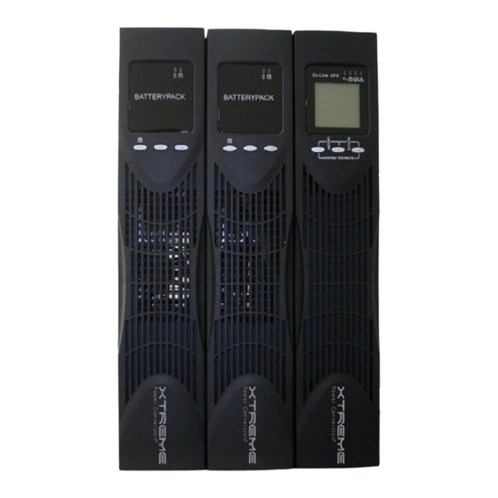
- Page 42 NXRTi USER’S MANUAL UNINTERRUPTIBLE POWER SUPPLY (UPS) NXRTi-1000 WITH (2) NXRTi-EBP1 Xtreme Power Conversion Corporation (Rev 8/29/13) Page 42...
-
Page 43: Led Description
The NXRT UPS System overcomes this limitation by equipping each extended battery pack (EBP) with its own charger, providing the user a way to achieve Xtreme Power Conversion Corporation (Rev 8/29/13) Page 43... - Page 44 2. The EBP’s use a cable shipped with each EBP to “daisy chain” together additional EBP’s to the first EBP being connected to the UPS in the appropriately labeled connector, or for connecting the first EBP to the UPS. Xtreme Power Conversion Corporation (Rev 8/29/13) Page 44...
-
Page 45: Extended Battery Pack Installation
AC utility to properly charge the batteries in a complete system. Leaving too many chargers connected may cause an over charge situation which could damage the batteries. 2. Which LED’s are supposed to be lit on the front of each EBP? Xtreme Power Conversion Corporation (Rev 8/29/13) Page 45... - Page 46 PLEASE DO NOT MIX EBP’s AND MAKE SURE YOU ONLY CONNECT THE EBP TO LIKE EBP’s OR UPS INDICATED ABOVE. DC VOLTAGES ARE MARKED ON BOTH THE UPS AND THE EBP – MAKE SURE THEY MATCH. Xtreme Power Conversion Corporation (Rev 8/29/13) Page 46...
- Page 47 NXRTi USER’S MANUAL UNINTERRUPTIBLE POWER SUPPLY (UPS) Xtreme Power Conversion Corporation (Rev 8/29/13) Page 47...
Need help?
Do you have a question about the NXRTi 1000VA and is the answer not in the manual?
Questions and answers