Table of Contents
Advertisement
Quick Links
Download this manual
See also:
Installation Manual
Advertisement
Table of Contents

Related Manuals for Octava HD4XSTPMX

Summary of Contents for Octava HD4XSTPMX
- Page 1 PRO HD HOME THEATER SERIES Model: HD4XSTPMX Installation Guide...
-
Page 2: Table Of Contents
Contents Application Diagram ............3 Features ................3 Matrix Front Panel Overview ..........4 Basic Front Panel Control ..........5 Matrix Back Panel Overview ........... 6 Zone Receiver (RX) Overview ........7 Infrared Overview ............8 Remote Control Guide ............ 9 Ethernet cable recommendations ......... -
Page 3: Application Diagram
Application Diagram Features: 4 inputs, up to 8 outputs (Installer configurable). Non-blocking Matrix – view Any Source on Any Display. 3D, 1080P, and 4K resolutions supported. Distributes HD video + Audio over single CAT6 cables up to 200ft (60m). -
Page 4: Matrix Front Panel Overview
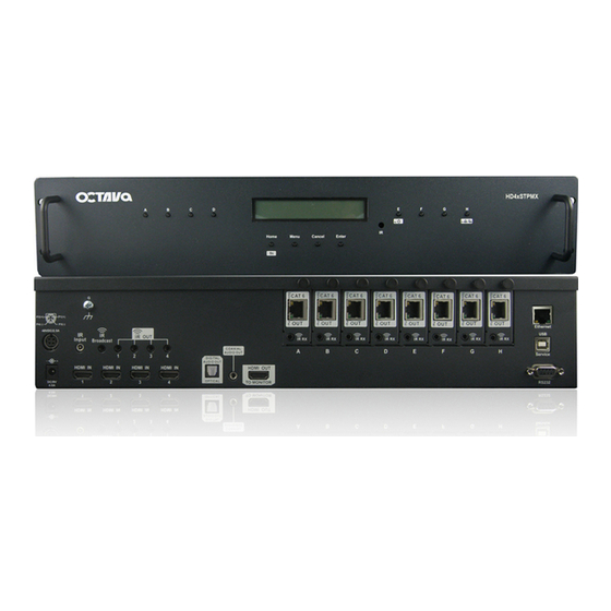
Matrix Front Panel Overview: 1-Output Select 2-Led Display 3- IR Receiver 4- Control and function select Item Description Output Select Press to switch inputs for output Zones LED Display IR Receiver IR receiver Control and function select... -
Page 5: Basic Front Panel Control
Basic Front Panel Control: Description LCD Display Turn On Turns On the matrix from the front panel Press fn+ power on/off matrix P o w e r Turn On/OFF Turns Off the matrix from the front panel Press fn+ power on/off matrix P o w e r O F F... -
Page 6: Matrix Back Panel Overview
Matrix Back Panel Overview: Item Description Power 48v (PoE) provides power to Octava PoE compatible Zone Receiver (Rx) units Power 9v (Matrix) provides power to Octava Matrix Wired IR input connect Octava supplied IR Receiver Extension cable ( optional) for hidden cabinet installs requiring line of sight for IR control. -
Page 7: Zone Receiver (Rx) Overview
Zone Receiver (RX) Overview: A Zone Rx unit is positioned close to your display device and connected to the Octava Matrix with a Twisted Pair (CAT6) cable. An Octava compatible Zone receiver must be used with the HD4xSTPMX Matrix. Compatible Zone Receiver: HD70STP-RX The HD70STP-RX Zone Receiver uses Power over Ethernet, PoE and is directly powered by the HD4xSTPMX over the CAT6 cable. -
Page 8: Infrared Overview
Infrared Overview: IR can be routed from any of the 8 connected Zones back to control: 1) the Matrix and 2) the connected Source devices. The Matrix also allows IR Routing + IR Broadcast for maximum utility. Routed IR: The IR Out 1-4 are "routed" for optimum IR control. For example, If Zone H is switched to HDMI Input 4. -
Page 9: Remote Control Guide
Remote Control Guide: 2 types of remotes are provided. Master Remote (Type C) and Zone Remote (Type D). The Master Remote (Type C) can fully control the matrix from any zone or directly in front of matrix The Zone Remote (Type D) is a simplified remote only allowing user to switch inputs for each zone. -
Page 10: Ethernet Cable Recommendations
Using shielded CAT6a or CAT7 cable will ensure maximum signal integrity plus optimum rejection of external interference. UTP CAT5 and CAT6 cables can be used with your Octava system though they may result in limiting the maximum attainable distance between the Matrix and the Rx unit when running HD signals. -
Page 11: Installation:basic Installation
Installation: Basic Installation Disconnect ALL Power cables from the MATRIX Disconnect ALL cables from the MATRIX / Zone Receivers Power OFF all HDTV/Displays/Audio Receivers Power OFF all Video Sources Power OFF Matrix Connect the 48VDC power supply to matrix Connect the 9VDC power supply to matrix... - Page 12 Connecting Output with CAT6 cables Connect CAT6 output A to Zone Receiver with CAT6a cable. Verify that the LED Indicator are illuminated as shown. Pwr LED = solid green Data LED = solid yellow Note 1* Connect HDMI output to Display Repeat step 7 and 9 for all Zones (Note 2*) * Note 2: If re-connecting the CAT6 cable to the matrix or receiver.
-
Page 13: Ir Installation
IR Installation I.R. Installation. Insert IR Receiver cable to the IR RX port of the Zone Receiver HD70STP-RX as shown. Insert IR Emitter cable to the IR Out ports of the Matrix HD70STPMX as shown. Connect a IR emitter cable to the IR Broadcast port if you need this feature. -
Page 14: Edid Configuration
EDID Configuration: The Octava Matrix can be configured to 5 EDID settings. It is recommended to keep the EDID in the default factory mode A. *Custom EDID mode can be downloaded via USB and stored as EDID mode E. Contact us for this feature. -
Page 15: Changing Edid Mode
Changing EDID mode: It is recommended to keep the EDID in the factory default MODE A. If necessary, you may set to different EDID mode by following these instructions. or view EDID Programming Instructions (video demo) at: www.octavainc.com/support and updates.html If you are unsure or need assistance, please contact us. -
Page 16: Scene Select
Scene Select: The HD4xSTPMX allows user to Quickly recall favorite Input/Output configurations. The default preset scenes are shown below. The scenes can be changed and programmed to meet your need. Scene IN/Out Configurations All outputs connected to Input 1 P r o g r a m... -
Page 17: Scene Programming
Remote control to S c e n e - A : 1 2 3 4 1 2 3 4 program the Scene for your preference. Use the Octava Remote Control to program the scenes Example: Programming Scene A Out A,E = 1 Out B.F= 2... -
Page 18: Usb Service Port
USB Service Port: The USB port is for service ,EDID updates or customization requests Contact us for this feature or visit out support page for more info www.octavainc.com/support and updates.html... -
Page 19: Serial Control
Serial Control: The HD4XSTP can be controlled by serial commands. Serial commands can be sent to the HD4xSTP by : 1) RS-232 port ( default) 2) LAN port Display Press Menu Button Goto Serial Control S e r i a l C o n t r o l P o r t >... -
Page 20: Serial Control Rs-232 Control Setup
Serial Control RS-232 Control Setup: The Matrix can be easily integrated with 3 Party control systems via RS232 control. The following shows the RS-232 pin out and control protocol for controlling the Matrix. RS-232 Port Pin 2 Receive Data Pin 3 Transmit Data Pin 5 Signal Ground... -
Page 21: Serial Control Via Lan Port Control Setup
NE-4100 support 10/100 Mbps Ethernet, and provide ready-to-use operation modes, including TCP Server, TCP Client, and UDP. This devices enables sending serial commands to the HD4XSTPMX using the LAN port. Once connected, and configured the RS-232 commands can be sent to control the HD4xSTPMX. - Page 22 Step Serial Control Via LAN Port Click "ADD" Click "Search" Continued on next page...
- Page 23 Step Serial Control Via LAN Port Wait for Search to complete. Make sure a device is found. If not, repeat step 1~6 Click “OK” Click “Yes” on the notification Wait until activation is complete Click “OK” on the notification Continued on next page...
- Page 24 Step Serial Control Via LAN Port Note the COM Port and IP Address Assigned as shown on your program screen. assigned IP address of Com Port Moxa Serial server Write down the COM Port = Write down the IP Address = Open “Local Area Connection Properties”...
- Page 25 Serial Control Via LAN Port Choose “Use the following IP address: -Key in the first 3 numbers from “Address 1” found in Step 12 for “IP address:” Enter "199" or some unused number for the 4th octet. -Key in 255.255.255.0 for “Subnet mask:” -Click “OK”...
-
Page 26: Serial Commands- (Basic)
Serial Commands- (Basic): Controlling the Matrix via RS232 can be done by send a series of commands per the RS232 Command Table Basic controls Note: The commands are in HEX. No spaces between HEX codes. “0x” denotes HEX. No need to enter “0x” HEX CODE Port Status 0x02... -
Page 27: Serial Commands- (Switching)
Serial Commands- (switching): Switching Commands Note: The commands are in HEX. No spaces between HEX codes. “0x” denotes HEX. No need to enter “0x” Output A Switching Commands HEX CODE Switch OUT A to Input port 1 0x02 0x32 0x31 0x31 0x03 Switch OUT A to Input port 2... - Page 28 Output G Switching Commands HEX CODE Switch OUT G to Input port 1 0x02 0x32 0x37 0x31 0x03 Switch OUT G to Input port 2 0x02 0x32 0x37 0x32 0x03 Switch OUT G to Input port 3 0x02 0x32 0x37 0x33 0x03 Switch OUT G to Input port 4...
-
Page 29: Serial Commands- (Forwarding)
Serial Commands- (Forwarding): The HD4xSTPMX can route commands from the RS-232 port to any connect Zones A-H for controlling the attached display The Forwarding protocol is shown here: Data Rate Zone # of bytes Start of 9600bps (0x41) A(0x31) 1(0xA1) -
Page 30: Zone Receiver Serial Data (Rs-232) Port
Zone Receiver Serial Data (RS-232) Port: The HD4xSTPMX can route commands from the RS-232 port to any connect Zones A-H for controlling the attached display A 3 pin Phoenix connector is provided to connect with a RS-232 serial cable. HD70STP... -
Page 31: Installing Transmitter Output Cards
Installing Transmitter Output cards : The HD4xSTPMX has configurable outputs allowing user to install additional cards. Step 4 Step1 Step 2 remove all cables from matrix Step 3 Step 5 Procedure Disconnect 48VDC and 9VDC power supply from the Matrix. - Page 32 Step 7 Step 6 Step 10 Step 9 Step 8 Procedure(cont'd) Remove the blank cover plate for the Output slot you wish to add. Out E shown. Install the TX card to the slot Install top cover back on matrix Tighten TX card thumb screws.
-
Page 33: Specifications
IR control of the Matrix, x4 Sources (Routed) plus an AVR from Zone receivers. Wideband IR 20-60 KHz circuitry for maximum IR remote compatibility using Octava supplied IR cables. RS-232 Control the Matrix using serial commands or 3 party control software (HEX commands available).. -
Page 34: Warranty
If Octava's equipment fails because of defects (1) year from the date of receipt, Octava will at its option, A) repair or replace the equipment, or B) request return of equipment for refund of the price paid for the product provided that the equipment has not been subjected to mechanical, electrical or other abuse or modifications.
Need help?
Do you have a question about the HD4XSTPMX and is the answer not in the manual?
Questions and answers