Table of Contents
Advertisement
Quick Links
IF YOU CANNOT READ OR UNDERSTAND THESE INSTALLATION INSTRUCTIONS DO NOT
INTRODUCTION
This remote control system was developed to provide a safe, reliable, and user-friendly remote control system for gas heating
appliance. The system can be operated thermostatically or manually from the transmitter. The system operates on radio frequencies
(RF) within a 20''range using non-directional signals. The system operates one of 1,048,576 security codes that are programmed into
the transmitter at the factory; the remote receiver's code must be matched to that of the transmitter prior to initial use.
Review COMMUNICATION SAFETY SECTION under TRANSMITTER section and THERMO SAFETY SECTION under REMOTE
RECEIVER section. These signal/temperature safety features shut down the fireplace system when a potentially unsafe condition exists.
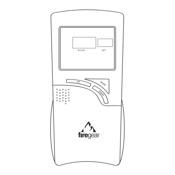
TRANSMITTER
ROOM
SET
LCD DISPLAY SCREEN
1
2
SU MO TU WE TH FR SA
PROGRAM
FOR
MORN DAY EVE NITE
4
ON
OFF
THERMO
PROGRAM
9
OVERRIDE HOLD
LOW
5
START
AM
AT
PM
TIME
TEMP
SET
TIMER
SWING
FLAME
10
12
INSTALLATION AND OPERATING INSTRUCTIONS
ATTEMPT TO INSTALL OR OPERATE
The transmitter operates on 2AAA-size 1.5V batteries. It is recommended that ALKALINE
batteries always be used for longer battery life and maximum operational performance.
IMPORTANT: New or fully charged batteries are essential for proper operation of the
multi-function transmitter.
ROOM
SET
Insert 2 AAA-size 1.5 V batteries into the battery transmitter, positioning the (+) and (-)
ends of the batteries as indicated on the casing. When the batteries are inserted, the
screen below (with similar numbers) will display.
Note: If a LOW battery icon appears on the screen, check the
position of the batteries.
Note: Due to the sensitive temperature-monitoring components
in the transmitter, it may be necessary to allow the transmitter to
stabilize to room temperature before accurate room temperatures
are displayed on the screen. If the transmitter is activated from a
severe cold condition, it can take up to fifteen minutes for accurate
temperature readings to appear.
1.
PROGRAM FOR: Flashes when programming days of week and periods of the
day. When in normal state, only current DAY displays. When programming or in
3
PROGRAM mode, both day and week will appear.
2.
DAY –Flashes when current day or day of week is being programmed.
3.
PERIOD – Flashes when current period of day or period of week is being
11
programmed.
13
4.
MODE – Indicates operation MODE of system.
7
•
6
•
•
14
8
•
5.
START AT – Flashes when programming the time to turn system ON.
6.
SET – Indicates desired SET room temperature, when in THERMO or
PROGRAM mode.
15
0
7.
8.
TIME/TEMP – Displays the CURRENT room temperature. In same frame, the
current time will display in AM or PM. You must depress the TIME/TIMER button
to display current time.
9.
LOW – Battery power is low. Replace batteries within 2 weeks.
10.
TIMER – When displayed, indicates countdown timer in operation.
11.
OVERRIDE – Displays when "programmed" SET temperature is overridden.
12.
FLAME – Single flame symbol indicates burner/valve is operational.
ON indicates the system is on, either manually, thermostatically, or
program.
Off indicates the entire system is turned off.
THERMO indicates the system will automatically cycle ON/OFF,
depending on programmed SET temperature.
PROGRAM – indicates the system is operating with PROGRAMMED
settings.
0
F /
C – Factory programmed in
FGP-305
O N O F F T H E R M O P R O G R A M
0
0
F. (
C indicates degrees in Celsius)
REV 8/21/06 Page 1 of 16
SU
TEMP
Advertisement
Table of Contents

Summary of Contents for Firegear FGP-305
- Page 1 FGP-305 INSTALLATION AND OPERATING INSTRUCTIONS IF YOU CANNOT READ OR UNDERSTAND THESE INSTALLATION INSTRUCTIONS DO NOT ATTEMPT TO INSTALL OR OPERATE INTRODUCTION This remote control system was developed to provide a safe, reliable, and user-friendly remote control system for gas heating appliance.
-
Page 2: Button Settings
13. HOLD – Displays when “programmed” SET temperature is overridden and will hold that temperature until cancelled. 14. CP – Displays when CHILD PROOF “LOCK OUT” is engaged. Pressing the UP and TIMER buttons together, engages CP. 15. SWING- Displays in SET frame when setting TEMPERATURE DIFFERNTIAL. FUNCTIONS O N O F F T H E R M O P R O G R A M To operate the system, press the MODE button on the transmitter to select the operational MODE... -
Page 3: Programming The Transmitter
SETTING THE CURRENT DAY OF THE WEEK Following Step 3 above, the symbol SU will begin flashing on the LCD screen. To change to the current day of the week Press the AHEAD or TIME BACK button on the front of the transmitter. After setting/confirming the current Day of the week, press the SET button on the front of the transmitter. -
Page 4: Programming Note
NOTE: If the above settings were not previously completed during the initial SET-UP and PROGRAMMING procedure, then the LCD screen will display SU, MORN, TIME and SET temperature digits. You must go back and perform the initial set-up procedure or the PROGRAM remote will not operate properly in the PROGRAM mode. -
Page 5: Program Review
PROGRAM REVIEW If you want to review the settings for either the FACTORY program PROGRAM MORN and/or your CUSTOMIZED program, you may do so by pressing the PROG button for one second. To review other settings, press the PROG button allowing one START second between each press of the PROG button. -
Page 6: Operating Instructions
OPERATIONAL NOTE: TO CONSERVE BATTERY POWER, CHANGES IN TEMPERATURE ARE ONLY RECORDED EVERY TWO MINUTES. Additionally, to prevent repeated thermo-cycling of the gas appliance, the sensing unit in the transmitter will only activate the remote receiver when the temperature change exceeds 2 F (1 C) above or below the SET (desired) temperature. - Page 7 To HOLD the new temperature at a CONSTANT setting, push the UP and DOWN buttons TOGETHER to activate the HOLD function. The word HOLD will appear over the SET frame and the word OVERRIDE will disappear. To cancel OVERRIDE or HOLD, press the SET button. TIME OF DAY DISPLAY To check the current TIME of day, press the TIMER/TIME button on the transmitter for less than 1 second.
-
Page 8: Remote Receiver
THERMO UPDATING FEATURE –TRANSMITTER This remote control has a THERMO UPDATING Feature built into its software. The THERMO UPDATING Feature operates in the following manner, but only in the THERMO and PROGRAM MODES: The transmitter normally reads the ROOM temperature every 2 minutes checking the ROOM temperature against the SET temperature it sends a signal to the receiver. -
Page 9: Installation Instructions
For REMOTE RECEIVERS that operate on BATTERY POWER, these heat conditions can cause batteries to discharge when temperatures exceed 115 F. Studies show that alkaline batteries, when exposed to a constant temperature of 115 F, can lose up to 50% of their operating power. When the battery cools down, it will partially recharge itself, but constant heating and cooling will reduce the battery’s normal life expectancy. -
Page 10: Wiring Instructions
To attach wall cover plate to receiver box: Position the receiver as shown in diagram to the left with lower tab on wall cover plate into groove of receiver (Make sure ADJ hole Cover Plate (Rear View) and LEARN hole on cover plate properly aligns with remote receiver) Remote Receiver Pull receiver up and snap into top tab of cover plate. -
Page 11: System Check
SYSTEM CHECK MILLIVOLT VALVES Light your gas appliance following the lighting instructions that came with the appliance. Confirm that the pilot flame is on; it must be in operation for the main gas valve to operate. • Slide the 3-position button on the remote receiver to the ON position. The main gas flame (i.e., the fire) should ignite. •... -
Page 12: Battery Life
BATTERY LIFE Life expectancy of alkaline batteries in the FGP-305 should be at least 12 months. Check and replace all batteries annually. When the Transmitter or Wall Transmitter no longer operates the receiver from a distance it did previously (i.e., the transmitter’s range has decreased) or the remote receiver does not function at all, the batteries should be checked. -
Page 13: Specifications
NOTE: THE MANUFACTURER IS NOT RESPONSIBLE FOR ANY RADIO OR TV INTERFERENCE CAUSED BY UNAUTHORIZED MODIFICATIONS TO THIS EQUIPMENT. SUCH MODIFICATIONS COULD VOID THE USER’S AUTHORITY TO OPERATE THE EQUIPMENT. FOR TECHNICAL U.S. INQUIRIES SERVICE, CALL: (888) 220-4333 Website: firegearusa.com MANUFACTURED EXCLUSIVELY FOR FIREGEAR REV 8/21/06 Page 13 of 16... - Page 14 REV 8/21/06 Page 14 of 16...
-
Page 15: Programme Settings
QUICK SET-UP GUIDE FOR FIREGEAR FGP-305 PROGRAMMABLE TRANSMITTER This guide is a “short cut” method to SETUP and OPERATE the programmable transmitter. For detailed instructions for each feature and function, see OWNER”S MANUAL. INITIAL SET-UPSET FUNCTIONS USING BUTTONS ON FRONT OFTRANSMITTER 1. - Page 16 QUICK PROGRAMMABLE GUIDE FOR FIREGEAR FGP-305 PROGRAMMABLE TRANSMITTER This guide is a “short cut” method to PROGRAM the operation of the programmable transmitter. For detailed instructions for each feature and function, see OWNER”S MANUAL. PROGRAMMING DAILY OPERATION PERIOD TIME/TEMP NOTE: A FACTORY PROGRAM is already installed in the transmitter’s software.
Need help?
Do you have a question about the FGP-305 and is the answer not in the manual?
Questions and answers