Kyocera FS-1030D Service Manual
Hide thumbs
Also See for FS-1030D:
- Operation manual (66 pages) ,
- Brochure & specs (4 pages) ,
- Command reference manual (410 pages)
Table of Contents
Advertisement
Quick Links
Advertisement
Table of Contents

Related Manuals for Kyocera FS-1030D


Summary of Contents for Kyocera FS-1030D
-
Page 1: Service Manual
FS-1030D SERVICE MANUAL Published in June 2007 842G6112 2G6SM002 Rev.2... - Page 2 Revision history Revision Date Replaced pages Remarks 20 December 2005 1-1-1 2-1-2, 2-4-3 28 June 2007...
-
Page 3: Safety Precautions
Safety precautions This booklet provides safety warnings and precautions for our service personnel to ensure the safety of their customers, their machines as well as themselves during maintenance activities. Service personnel are advised to read this booklet carefully to familiarize themselves with the warnings and precautions described here before engaging in maintenance activities. - Page 4 Safety warnings and precautions Various symbols are used to protect our service personnel and customers from physical danger and to prevent damage to their property. These symbols are described below: DANGER: High risk of serious bodily injury or death may result from insufficient attention to or incorrect compliance with warning messages using this symbol.
-
Page 5: Installation Precautions
1. Installation Precautions WARNING Do not use a power supply with a voltage other than that specified. Avoid multiple connections to one outlet: they may cause fire or electric shock. When using an extension cable, always check that it is adequate for the rated current..................... Connect the ground wire to a suitable grounding point. -
Page 6: Specifications 1
2. Precautions for Maintenance WARNING Always remove the power plug from the wall outlet before starting machine disassembly....Always follow the procedures for maintenance described in the service manual and other related brochures............................Under no circumstances attempt to bypass or disable safety features including safety mechanisms and protective circuits. - Page 7 Do not pull on the AC power cord or connector wires on high-voltage components when removing them; always hold the plug itself....................... Do not route the power cable where it may be stood on or trapped. If necessary, protect it with a cable cover or other appropriate item.
- Page 8 This page is intentionally left blank.
-
Page 9: Table Of Contents
CONTENTS 1-1 Specifications 1-1-1 Specifications ............................1-1-1 1-1-2 Name of parts ............................1-1-3 (1) Overall ............................1-1-3 (2) Operation panel ..........................1-1-4 1-1-3 Machine cross section ......................... 1-1-5 1-2 Handling Precautions 1-2-1 Process unit (drum) ..........................1-2-1 1-2-2 Installation environment ........................1-2-1 1-3 Installation 1-3-1 Unpacking and installation ........................ -
Page 10: Assembly And Disassembly
(10) The heater lamp does not turn off....................1-5-19 (11) Main charging is not performed....................1-5-19 (12) Transfer charging is not performed....................1-5-19 (13) A paper jam in the paper feed or exit section is indicated when the power switch is turned on..................... 1-5-19 (14) The LED indicator requesting covers to be closed is displayed when the front cover is closed. - Page 11 (1-1) Process unit mechanism ....................... 2-1-7 (2) Main charging ..........................2-1-8 (2-1) Photo conductive drum ......................2-1-8 (2-2) Charging the drum ......................... 2-1-9 (3) Exposure ............................2-1-10 (3-1) Laser scanner unit ....................... 2-1-11 (3-2) Drum surface potential ......................2-1-12 (4) Development ..........................2-1-13 (5) Transfer ............................
- Page 12 This page is intentionally left blank. This page is intentionally left blank.
-
Page 13: Specifications
2G6-1 1-1-1 Specifications Type ..........Desktop Printing system ......Electrophotography using laser scan Paper type ........Cassette: Plain paper, recycled paper, thick paper: 60 to 105 g/m MP tray: Plain paper, recycled paper, thick paper: 60 to 163 g/m Note: Transparency, adhesive backed labels, envelopes and post cards supported Paper size ........ - Page 14 Controller software ......a) Emulation PCL6 (PCL5e + PCLXL) KPDL3 (PostScript 3 compatible) b) Fonts: Bitmap font: 1 Line Printer bitmap font Outline fonts: 35 PCL6 (PCL5e/PCL-XL) fonts 45 KPDL2 fonts: c) Graphic: (1) Raster graphic: 75, 100, 150, 200*, 300, 600* dpi (*200 dpi is supported when the resolution is 600 dpi.) (2) Vector graphic: Line, Box, Circle, Arc, Fill pattern etc.
-
Page 15: Name Of Parts
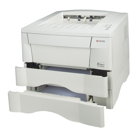
1-1-2 Name of parts (1) Overall Figure 1-1-1 1. Top cover 10. Extension tray 2. Front cover 11. Power switch 3. Process unit 12. Memory cover 4. Toner container 13. Rear cover 5. Main charger cleaner 14. Optional interface slot 6. - Page 16 (2) Operation panel Figure 1-1-2 1. Ready indicator (Green) 2. Data indicator (Green) 3. Attention indicator (Red) 4. Toner indicator (Red) 5. CANCEL key 6. GO key 1-1-4...
-
Page 17: Machine Cross Section
1-1-3 Machine cross section Printer Option paper feeder Cassette, MP tray Paper path Optional paper feeder Switchback and refeed (duplex printing) Figure 1-1-3 1. Cassette 7. Transfer section 2. Paper feed unit 8. Fuser unit 3. MP tray 9. Output tray 4. - Page 18 This page is intentionally left blank. 1-1-6...
-
Page 19: Process Unit (Drum)
1-2-1 Process unit (drum) Note the following when handling or storing the drum. When removing the process unit, never expose the drum surface to strong direct light. Keep the drum at an ambient temperature between 10°C/50°F and 32.5°C/90.5°F and at a relative humidity not higher than 80% RH. - Page 20 This page is intentionally left blank. 1-2-2...
-
Page 21: Unpacking And Installation
1-3-1 Unpacking and installation (1) Installation procedure Start Unpack. Remove the tape and protective packing. Install a toner container. Connect the printer cable and power cord. Load paper. Initializing the printer and make test print (status page). Loading software. Printing a document. Completion of the machine installation. - Page 22 Unpack Figure 1-3-1 Unpacking 1. Printer 2. Power cord 3. Installation guide 4. Toner container 5. Cleaning cloth 6. CD-ROMs 7. Extension tray [For inch model only] 1-3-2...
- Page 23 Remove the tape and protective packing 1. Remove the two tape. Tape Figure 1-3-2 2. Pull the cassette out of the printer. 3. Remove the protective packing from inside the cassette. Protective packing Cassette Figure 1-3-3 1-3-3...
- Page 24 Install a toner container. Lock lever 1. Open the top cover. 2. Move the lock lever until it is in its unlocked position (marked [UNLOCK]). Top cover Figure 1-3-4 3. Shake the toner container horizontally back and forth five or six times so that the toner inside of it becomes evenly distributed.
- Page 25 Toner container 5. Set the toner container into the process unit. Process unit Figure 1-3-7 6. Push in on the areas of the toner container marked Toner container [PUSH HERE] until the container clicks into place in the process unit. Figure 1-3-8 Lock lever 7.
- Page 26 Connect the printer cable and power cord. 1. Connect the printer cable (parallel or USB). Parallel interface connector Parallel printer cable USB interface connector USB cable Figure 1-3-10 2. Connect the power cord. Power cord AC inlet Figure 1-3-11 1-3-6...
- Page 27 Load paper. 1. Pull the cassette out of the printer. 2. Set the paper in the cassette. Cassette Figure 1-3-12 Initializing the printer and make test print (status page). 1. Turn on the printer's power switch. Upon turning on the power, the printer's 4 indicators flash in sequence until printer initialization is complete, then the indicator [on line] lights steadily.
- Page 28 Print dialog box displays. 3. Select the drop down list of printer names. All the printers installed are listed. Select the FS-1030D. 4. Select the options required, enter the number of copies required and if printing more than one set, select Collate.
-
Page 29: Installing The Expanding Memory (Option)
1-3-2 Installing the expanding memory (option) The main board of the printer is equipped with one socket for memory expansion. Expansion memory is available in the form of DIMM (Dual In-line Memory Module). CAUTION Take precautions that no foreign substances such as metal chips or liquid get inside the printer during the Memory socket Clip... -
Page 30: Installing The Memory Card (Option)
1-3-3 Installing the memory card (option) The main board of the printer is equipped with one slot for memory card. CAUTION Take precautions that no foreign substances such as metal chips or liquid get inside the printer during the installation process. Operation of the printer during the presence of a foreign substance may lead to fire or electric shock. -
Page 31: Installing The Network Interface Card (Option)
1-3-4 Installing the network interface card (option) If the serial interface board kit is installed, remove it to use the network interface card. CAUTION Take precautions that no foreign substances such as metal chips or liquid get inside the printer during the installation process. - Page 32 This page is intentionally left blank. 1-3-12...
-
Page 33: Maintenance
1-4-1 Maintenance The product incorporates several service modes which are activated by using the keys on the operator panel or by com- manding from a PC. (1) Executing service mode Printing a service status page ......See page 1-4-2. Printing an event log (EVENT LOG) ....See page 1-4-5. 1-4-1... - Page 34 Service items Description Printing a service Description status page Prints a service status page for service purpose. The service status page includes various printing settings and service cumulative. Purpose To acquire the current printing environmental parameters and cumulative information. Procedure To print a service status page, using the GO key on the operator panel.
- Page 35 Bit 0 = 1: (Fixed) Bit 1 = 0: Overseas, 1: Domestic (Japan) Bit 2, 3 (Not used) Bit 4 = 0: Kyocera, 1: OEM Bit 5 = 0: For Europe, 1: For US Bit 6 = 0: Non MICR mode, 1: MICR mode...
- Page 36 Service items Description Item Description Total page Total print page count Toner install mode Parallel I/O information Serial I/O error code 00: Normal Bit 0: Framing error Bit 1: Overrun error Bit 2: Parity error USB information 00: Not connected 01: Full-Speed 02: Hi-Speed Operator panel lock status...
- Page 37 Service items Description Printing an event log Description (EVENT LOG) Prints a history list of occurences of paper jam, self-diagnostics, toner replacements, etc. Purpose Analyze the failure by determining the cause depending on the history of occurrence. Procedure 1. Connect the USB or parallel cable between printer and PC. 2.
- Page 38 1 = 0: Overseas, 1: Domestic (Japan) [First byte/second byte bit 2, 3 (Not used) (displayed in OEM mode bit 4 = 0: Kyocera, 1: OEM only)] bit 5 = 0: For Europe, 1: For US bit 6 = 0: Non MICR mode, 1: MICR mode...
- Page 39 Service items Description Items Description Paper Jam Log (a) Cause of paper jam 10: Paper does not arrive at the registration sensor. [42] (MP tray) 10: Paper does not arrive at the registration sensor. [43] (Cassette 1) 10: Paper does not arrive at the registration sensor. [44] (Cassette 2) 10: Paper does not arrive at the registration sensor.
- Page 40 Service items Description Items Description Paper Jam Log (d) Detail of paper size (Hexadecimal) 00: (Undefined) 23: Special 2 0B: B4 01: Monarch 24: A3 wide 0C: Ledger 02: Business 25: Ledger wide 0D: A5 03: International DL 26: Full bleed paper (12 0E: A6 04: International C5 0F: B6...
- Page 41 Service items Description Items Description Service Call Log Count. Service Code (Self diagnostic Remembers 1 to 8 of oc- The total page count at See page 1-5-3. error) currence of self diagnos- the time of the self diag- tics error. If the occur- nostics error.
- Page 42 This page is intentionally left blank. 1-4-10...
-
Page 43: Paper Misfeed Detection
1-5-1 Paper misfeed detection (1) Paper misfeed indication If a paper jam occurs while printing, the printer notifies it by the following combination of the four indicators. Remove the jammed paper as described below. After removal, open and close the top cover once to initialize the jam sensing. (Off) (Lit) Green... -
Page 44: Self-Diagnosis
1-5-2 Self-diagnosis (1) Self-diagnostic function Service errors are represented by the alternating flashing of the indicators (LEDs). Each error is represented by the notation of four digits code and can be monitored on the Remote Operation Panel utility. e.g. Call service 2000 is for the main motor error. - Page 45 Code Error indications Contents 2000 Main motor error Check procedures/corrective measures START Remove and check harness (2DC2711) between engine PWB (K0010) and main motor at pins 6 to 9 on both ends. Connect circuit tester to pin 8 (MOTORN) of YC04 on engine PWB +24 V DC at (K0010) and ground.
- Page 46 Code Error indications Contents 4000 Laser scanner unit [Polygon motor] error Check procedures/corrective measures START Replace engine PWB +24 V DC at pin 5 of (K0010). See page 1-6- YC06 on engine PWB (K0010) ? Replace laser scanner Replace engine PWB unit.
-
Page 47: K0010). See
Check procedures/corrective measures Continued from previous page. Replace engine PWB (K0010). See page 1-6- Turn power switch on. Replace main PWB (K0011). See page 1-6- End. Turn power switch on. End. Replace harness (2FM2602) between engine PWB and main PWB. 1-5-5... -
Page 48: Does Pin
Code Error indications Contents 4200 Laser scanner unit [Pin photo diode] error Check procedures/corrective measures START +5 V DC at pin 6 of YC07 on main PWB (K0011) ? Replace main PWB (K0011). See page 1-6- Connect oscilloscope to pin 4 (OUTPEN) of YC07 on main PWB (K0011). -
Page 49: Unit. See
Check procedures/corrective measures Continued Continued from previous page. from previous page. Replace main PWB Replace laser scanner (K0011). See page 1-6- unit. See page 1-6-28. Replace main PWB Turn power switch on. (K0011). See page 1-6- Turn power switch on. Replace harness (2DC2714) between End. - Page 50 Code Error indications Contents 6000 Fuser unit error Check procedures/corrective measures START Turn power switch off, and remove power cable. Detach connector CN4 on power supply unit. Measure resistance between pins 1 and 2 of the detached connector. Replace engine PWB Open (infinite)? (K0010).
- Page 51 Code Error indications Contents 7980 Waste toner full [Total page count less than 100,000 pages of printing] Check procedures/corrective measures START Shake the process unit horizontally. Turn power switch off, then on. "7980" error shown? Replace the process unit. Turn power switch off, then on.
- Page 52 Code Error indications Contents 7990 Waste toner full [Total page count more than 100,000 pages of printing] Check procedures/corrective measures START Shake the process unit horizontally. Turn power switch off, then on. "7990" error shown? Replace the process unit. End. Turn power switch off, then on.
- Page 53 Check procedures/corrective Contents Code Error indications measures F010 Controller checksum Turn power switch off, then on. If not error solved, replace main PWB (See page 1-6-10). F020 Controller RAM read/ Remove the expansion memory write error (DIMM). Turn power switch off, then on.
-
Page 54: Image Formation Problems
1-5-3 Image formation problems (1) No image appears (2) No image appears (3) Image is too light. (4) Background is visible. (entirely white). (entirely black). See page 1-5-13 See page 1-5-13 See page 1-5-13 See page 1-5-14 (8) One side of the print (5) A white line appears (7) A black line appears (6) A black line appears... - Page 55 (1) No image appears Causes (entirely white). 1. Defective process unit installation. 2. No transfer charging. 3. Defective laser scanner unit. Causes Check procedures/corrective measures 1. Defective process unit installation. Check that the process unit is inserted correctly. 2. No transfer charging. Check the transfer bias output on the high voltage unit.
- Page 56 (4) Background is visible. Causes 1. Defective print density setting. 2. Defective surface potential of the drum. 3. Defective developing roller. Causes Check procedures/corrective measures 1. Defective print density setting. Open the printer top cover and check that the process unit is correctly seated.
- Page 57 (6) A black line appears Causes longitudinally. 1. Contaminated main charger wire. 2. Dirty or flawed drum. 3. Deformed or worn cleaning blade. 4. Defective magnet roller (in the process unit). Causes Check procedures/corrective measures 1. Contaminated main charger wire. Clean the main charger wire by pulling the green colored cleaning knob in and out several times.
-
Page 58: Image Is Blurred
(9) Black dots appear Causes on the image. 1. Dirty or flawed drum. 2. Dirty contact glass. 3. Deformed or worn cleaning blade. Causes Check procedures/corrective measures 1. Dirty or flawed drum. Replace the process unit. 2. Dirty contact glass. Clean the contact glass. -
Page 59: Offset Occurs
(12) Offset occurs. Causes 1. Defective cleaning blade. Causes Check procedures/corrective measures 1. Defective cleaning blade. Replace the process unit. (13) Image is partly miss- Causes ing. 1. Paper damp. 2. Paper creased. 3. Flawed drum. Causes Check procedures/corrective measures 1. -
Page 60: Electrical Problems
1-5-4 Electrical problems Problem Causes Check procedures/corrective measures No electricity at the power Measure the input voltage. The machine does outlet. not operate when The power cord is not Check the contact between the power plug and the outlet. the power switch is plugged in properly. -
Page 61: The Heater Lamp Does Not Turn On
Problem Causes Check procedures/corrective measures Broken registration sole- Check for continuity across the coil. If none, replace the regis- The registration so- noid coil. tration solenoid. lenoid does not op- Poor contact in the regis- Reinsert the connector. Also check for continuity within the con- erate. -
Page 62: A Paper Jam In The Paper Feed Or Exit Section Is Indicated When The Power Switch Is Turned On
Problem Causes Check procedures/corrective measures A piece of paper torn from (13) Check and remove if any. copy paper is caught A paper jam in the paper feed or exit around registration sensor section is indicated or exit sensor. when the power Defective registration sen- Replace registration sensor if indication of the corresponding switch is turned on. -
Page 63: Mechanical Problems
1-5-5 Mechanical problems Problem Causes/check procedures Corrective measures Check if the surfaces of the feed roller and Clean with isopropyl alcohol. No primary paper feed. MP feed roller are dirty with paper powder. Check if the feed roller and MP feed roller Check visually and replace any deformed are deformed. - Page 64 This page is intentionally left blank. 1-5-22...
-
Page 65: Precautions For Assembly And Disassembly
1-6-1 Precautions for assembly and disassembly (1) Precautions Be sure to turn the power switch off and disconnect the power plug before starting disassembly. When handling PWBs (printed wiring boards), do not touch parts with bare hands. The PWBs are susceptible to static charge. -
Page 66: Removing The Process Unit
1-6-2 Removing the process unit 1. Open the front top cover. 2. Open the front cover. 3. Lift the process unit together with the toner container out of the printer. Front top cover Front cover Process unit Figure 1-6-1 Removing the process unit CAUTIONS After removing the process unit, seal it in the protective bag and place it on flat surface. -
Page 67: Removing The Principal Outer Covers
1-6-3 Removing the principal outer covers (1) Removing the top cover/output tray 1. Open the top cover. 2. Remove two screws. 3. Remove the top cover/output tray. Top cover Screws Top cover/output tray Figure 1-6-2 Removing the top cover/output tray 1-6-3... -
Page 68: Removing The Right Cover
(2) Removing the right cover 1. Remove one screw. 2. Remove the side cover. 3. Unlatch the six snaps and one hook hole on the chassis, remove the right cover. Right cover Right cover Screw Snap/Hook Side cover (inside cover) Figure 5-2-3 Removing the right cover (3) Removing the left cover 1. -
Page 69: Removing The Feed Roller
1-6-4 Removing the feed roller CAUTION When refit the feed roller, fit the D-cut shaft into the D-shape hole of the feed roller. 1. Remove the paper cassette and the process unit. (See page 1-6-2) 2. Stand the machine the front side up. 3. -
Page 70: Removing The Mp Feed Roller
1-6-5 Removing the MP feed roller 1. Remove the engine PWB (See page 1-6-9). 2. Remove wires from the wire saddles. 3. Remove one screw and then remove the cord cover. 4. Remove the one screw. 5. Remove the grounding plate. 6. - Page 71 6. Remove one screw. 7. Remove the toner sensor and spring. 8. While pressing the latch by using the driver and then remove the paper guide. 9. Remove two screws and then remove the MP feed unit. Paper guide Screw oner sensor Paper guide Spring...
-
Page 72: Removing The Transfer Roller
1-6-6 Removing the transfer roller CAUTION Do not touch the transfer roller (sponge) surface. Oil and dust (particles of paper, etc.) on the transfer roller can significantly deteriorate the print quality (white spots, etc.). When refitting the bushes and springs, make sure to refit the black colored bush and spring on the left side. Also, observe the correct direction to which the bush is fit in reference to the paper passing direction. -
Page 73: Removing The Principal Pwbs
1-6-7 Removing the principal PWBs (1) Removing the engine PWB 1. Remove the right cover (See page 1-6-4). 2. Remove all (twelve) connectors from the engine PWB. 3. Remove three screws. 4. Remove the engine PWB. * When replacing the PWB with a new PWB, remove the EEPROM (U2) from the old PWB and mount it to the new PWB. -
Page 74: Removing The Main Pwb
(2) Removing the main PWB 1. Remove the process unit (See page 1-6-2). 2. Remove the top cover/face-down output tray and right cover (See pages 1-6-3 and 1-6-4). 3. Remove two connectors from main PWB. 4. Remove six screws. 5. Remove the controller box (with main PWB). Screws Connector Screws... - Page 75 6. Remove two screws at the back of the main PWB. 7. Remove three screws from the parallel interface connector and USB connector. 8. Remove the main PWB. Screws Main PWB USB interface connector Parallel interface connector Screws Controller box Figure 1-6-12 Removing the main PWB 1-6-11...
-
Page 76: Removing The Power Supply Unit And High Voltage Unit
(3) Removing the power supply unit and high voltage unit 1. Remove the process unit (See page 1-6-2). 2. Remove the left cover (See page 1-6-4). 3. Remove three connectors from the power supply unit. 4. Remove nine screws. 5. Remove the power supply unit and high voltage unit. (Note: The high voltage unit is directly connected to the bias PWB.) 6. -
Page 77: Removing The Bias Pwb
(4) Removing the bias PWB 1. Remove the cassette and process unit (See page 1-6-2). 2. Remove the left cover (See page 1-6-4). 3. Remove the power supply unit and high voltage unit (See the previous page). 4. Turn the machine with the bottom side up. 5. - Page 78 7. Remove five screws. 8. Remove the bottom cover. 9. Remove the three connectors from the bias PWB. 10. Remove the bias PWB. Bottom cover Screws Screws Connectors Bias PWB Connector Figure 1-6-15 Removing the bias PWB 1-6-14...
-
Page 79: Removing The Main Motor And Drive Unit
1-6-8 Removing the main motor and drive unit 1. Remove the cassette and process unit (See page 1-6-2). 2. Remove the right cover (See page 1-6-4). 3. Remove three connectors from the main motor. 4. Remove four screws. 5. Remove main motor. Connectors Main motor Screws... - Page 80 6. Remove the engine PWB (See page 1-6-9). 7. Remove wires from wire saddles on the cord cover. 8. Remove one screw. 9. Remove the cord cover. Wire saddle Screw Wire saddles Cord cover Figure 1-6-17 Removing the cord cover 1-6-16...
- Page 81 10. Remove the main PWB (See page 1-6-10). 11. Remove one screw and then remove the grounding plate. 12. Remove one screw and then remove the feed solenoid. 13. Remove three stop rings. 14. Remove MP feed clutch (gear), feed clutch (gear), and registration clutch (gear). MP feed clutch (gear) Stop ring Grounding...
- Page 82 15. Remove the four screws. 16. Remove the drive unit. Drive unit Screws Screws Figure 1-6-19 Removing the drive unit 1-6-18...
-
Page 83: Removing And Splitting The Fuser Unit
1-6-9 Removing and splitting the fuser unit WARNING The fuser unit is hot after the printer was running. Wait until it cools down. CAUTION When refitting the fuser unit, make sure the fuser unit gear and the printer’s drive gear are properly meshed with each other. - Page 84 6. Remove two screws. 7. Open and split the fuser unit. Screw Fuser unit Screw Figure 1-6-21 Splitting the fuser unit 1-6-20...
-
Page 85: Removing The Separation Craws
(1) Removing the separation claws WARNING The separation claws are extremely hot immediately after the printer was running. Allow substantial period of time until it cools down. 1. Remove and split the fuser unit (See page 1-6-19). 2. Loosen the stopper screws. 3. -
Page 86: Removing The Heater Lamp
(2) Removing the heater lamp WARNING The heater lamp is extremely hot immediately after the printer was running. Allow substantial period of time until it cools down. Also, the heater lamp is fragile: Handle it with great care. CAUTION The heater lamps are fragile. Use extreme care when handling not to drop or break. Do not directly touch on the heater lamp. -
Page 87: Removing The Heat Roller
(3) Removing the heat roller WARNING The heat roller is extremely hot immediately after the printer was running. Allow substantial period of time until it cools down. 1. Remove and split the fuser unit (See page 1-6-19). 2. Remove the heater lamp (See previous page). 3. - Page 88 4. Remove the heat gear Z33, heat R bush, and heat L bush from the heat roller. Heat L bush Heat roller Heat R bush Heat gear Z33 Figure 1-6-25 Removing the heat roller 1-6-24...
-
Page 89: Removing The Fuser Thermistor
(4) Removing the fuser thermistor 1. Remove and split the fuser unit (See page 1-6-19). 2. Remove the heater lamp (See page 1-6-22). 3. Remove the heat roller (See page 1-6-23). 4. Remove one screw. 5. Remove the fuser thermistor. Screw Fuser thermistor Figure 1-6-26 Removing the fuser thermistor... -
Page 90: Removing The Thermal Cutout
(5) Removing the thermal cutout CAUTION Do not bend the terminals of the thermal cutout. 1. Remove and split the fuser unit (See page 1-6-19). 2. Remove the heater lamp (See page 1-6-22). 3. Remove the heat roller (See page 1-6-23). 4. -
Page 91: Removing The Press Roller
(6) Removing the press roller WARNING The press roller is extremely hot immediately after the printer was running. Allow substantial period of time until it cools down. 1. Remove and split the fuser unit (See page 1-6-19). 2. Remove the press roller from the fuser unit. Press roller Fuser unit Figure 1-6-28 Removing the press roller... -
Page 92: Removing The Laser Scanner Unit And The Eraser Lamp
1-6-10 Removing the laser scanner unit and the eraser lamp 1. Remove the right cover and left cover (See page 1-6-4). 2. Remove four connectors. 3. Remove the scanner seal. 4. Remove six screws and then remove the LSU shield. * When refitting the LSU shield, tighten a screw in order of from... - Page 93 4. Remove three screws. 5. Remove two connectors from the laser scanner unit. 6. Remove the laser scanner unit. * When refitting the laser scanner unit, tighten a screw in order of from Screws Laser scanner unit Conncetor Conncetor Figure 1-6-30 Removing the laser scanner unit 1-6-29...
- Page 94 7. Remove the eraser lamp. Eraser lamp 1-6-31 Removing the eraser lamp 1-6-30...
-
Page 95: Removing The Main Charger Unit
1-6-11 Removing the main charger unit 1. Remove the process unit from the printer (See page 1-6-2). 2. Unlatch the three snaps, and remove the main charger cap. 3. Draw the main charger unit in the direction of arrow (A), then pull it out in the direction of arrow (B). Main charger unit Snap Snaps... - Page 96 This page is intentionally left blank. 1-6-32...
-
Page 97: Upgrading The Firmware On The Main Pwb
1-7-1 Upgrading the firmware on the main PWB Updating the system (controller) firmware is possible by downloading the firmware through the parallel interface or through the memory card (CompactFlash). These firmware programs are directly overwritten in the system DIMM (Flash ROM type only) on the main PWB. -
Page 98: Downloading The Firmware From The Parallel Interface
(2) Downloading the firmware from the parallel interface This section explains how to download firmware data from the parallel interface. The printer system can automatically recognize whether the data to be overwritten is for controller firmware. CAUTION Downloading the firmware takes several minutes. -
Page 99: Downloading The Firmware From The Memory Card
(3) Downloading the firmware from the memory card To download data written in a memory card (CompactFlash) to the printer, proceed as explained in this section. CAUTION Downloading firmware takes several minutes. Do not turn power off during downloading. If downloading is interrupted by an accidental power failure, etc., the system DIMM may have to be replaced. -
Page 100: Downloading Errors
(4) Downloading errors The following downloading errors are indicated on LED indicators when an error occurred during downloading the firmware data. Download finished Download errors normally Cause LED indicators LED indicators Description Corrective action Download Deficit of a file header Obtain normal firmware. -
Page 101: Paper Feeding System
2-1-1 Paper feeding system The paper feeding system picks up paper from the cassette, MP tray, or if installed, the paper feeder, feeds it in the printer, and delivers in the output tray. Paper is fed at the precise timing in synchronization with data processing. The paper feeding system finally delivers the printed page to either the face-down or face-up tray as manipulated by the user. -
Page 102: Paper Feed Control
2G6-2 (1) Paper feed control The following diagram shows interconnectivity of the feeding system components including the sensors and rollers. The engine board provides the signals in conjunction with the electrophotography process that is driven by the main board. Engine PWB DUDR1 YC13-1 Switchback... -
Page 103: Paper Feeding Mechanism
(2) Paper feeding mechanism Driving power train (A) For process unit; drum (From main unit) (B) From process unit; drum (To transfer roller) Figure 2-1-3 Paper feeding mechanism 1. Main motor (gear) 12. Transfer roller 2. Registration clutch 13. TC gear Z18 3. -
Page 104: Switchback/Refeed System
(3) Switchback/refeed system Paper that has already being fixed in the fuser unit on its first (front) side will be conveyed along the guide towards the face- down tray via the turning of the fuser unit’s lower exit roller. At this point, the fuser unit’s upper exit roller is turning in a forward direction and, in the case of 1-sided printing, the paper will be ejected onto the face-down tray through the normal action of that upper exit roller. - Page 105 Upper exit roller forward/reverse mechanism Output tray (face-down) Exit roller gear Upper exit roller Idle Latch lever gear From switchback solenoid Drive train from main motor Switchback Paper exit roller (gear) Upper exit roller Idle From gear switchback solenoid Latch lever Drive train from main motor Figure 2-1-5 Upper exit roller forward/reverse drive mechanism...
-
Page 106: Electrophotographic System
2-1-2 Electrophotographic system Electrophotography is the technology used in laser printing which transfer data representing texts or graphics objects into a visible image which is developed on the photosensitive drum, finally fusing on paper, using light beam generated by a laser diode. This section provides technical details on the printer’s electrophotography system. -
Page 107: Process Unit Mechanism
(1-1) Process unit mechanism Driving power train (A) For drum [From main unit] (B) For main unit [Transfer roller] (C) For toner container Figure 2-1-7 Process unit mechanism 1. Main charger unit 12. DLP screw B 2. Charger wire 13. DLP screw A 3. -
Page 108: Main Charging
(2) Main charging (2-1) Photo conductive drum The durable layer of organic photoconductor (OPC) is coated over the aluminum cylinder base. The OPC tend to reduce its own electrical conductance when exposed to light. After a cyclic process of charging, exposure, and development, the electrostatic image is constituted over the OPC layer. -
Page 109: Charging The Drum
(2-2) Charging the drum The following shows a simplified diagram of the electrophotographic components in relation to the engine system. Charging the drum is done by the main charger unit (A). High voltage unit Bias Engine PWB MHVDR MHVDR1 YC-M YC11-5 CN2-A4 PSEL2... -
Page 110: Exposure
(3) Exposure The charged surface of the drum (A) is then scanned by the laser beam from the laser scanner unit (B). Laser beam (LSU) Figure 2-1-10 Exposure The laser beam (780 nm wavelength) beam is dispersed as the polygon motor (polygon mirrors) revolves to reflect the laser beam over the drum. -
Page 111: Laser Scanner Unit
(3-1) Laser scanner unit Diversion mirror Figure 2-1-11 Laser scanner unit 1. Laser diode ............ Emits diffused, visible laser. 2. Cylindrical lens ..........Compensates the vertical angle at which the laser beam hits a polygon mirror segment. 3. Polygon mirror (motor) ........Has six mirror segments around its hexagonal circumference; each mirror corresponding to one scanned line width on the drum when laser beam scans on it. -
Page 112: Drum Surface Potential
(3-2) Drum surface potential The laser beam is continually switched on and off depending on the print data. It is on for a black (exposed) dot and off for a white (blank) dot. Since the drum surface is evenly charged, whenever it is illuminated by the laser beam, the electrical resistance of the photoconductor is reduced and the potential on the photoconductor is also lowered. -
Page 113: Development
(4) Development The latent image constituted on the drum is developed into a visible image. The developing roller (A) contains a 3-pole (S-N-S) magnet core (B) and an aluminum cylinder rotating around the magnet core (B). Toner attracts to the developing roller (A) since it is powdery ink made of black resin bound to iron particles. -
Page 114: Transfer
(5) Transfer The image developed by toner on the drum (A) is transferred onto the paper because of the electrical attraction between the toner itself and the transfer roller (B). The transfer roller is negatively biased so that the positively charged toner is attracted onto the paper while it is pinched by the drum and the transfer roller. -
Page 115: Fusing
(6) Fusing The toner on the paper is molten and pressed into the paper as it passes between the heat roller (A) and the press roller (B) in the fuser unit. Figure 2-1-15 Fusing The heat roller has a halogen lamp inside which continuously turns on and off by the thermistor to maintain the constant temperature onto the heat roller surface. -
Page 116: Fuser Unit Mechanism
(6-1) Fuser unit mechanism Figure 2-1-16 Fuser unit mechanism 1. Heat roller 7. Heater lamp 2. Idle gear Z34 8. Thermal cutout 3. Exit gear Z23 9. Separator(s) 4. Idle gear Z18 10. Thermistor 5. Heat gear Z33 11. Exit pulley(s) 6. -
Page 117: Cleaning
(7) Cleaning After the transferring process, the drum needs to be physically cleaned of toner which is residual after the development process. The cleaning blade (A) is constantly pressed against the drum (B) and scrapes the residual toner off to the sweep roller (C). - Page 118 This page is intentionally left blank. 2-1-18...
-
Page 119: Electrical Parts Layout
2-2-1 Electrical parts layout (1) Electrical parts layout Figure 2-2-1 Electrical parts layout 1. Main PWB (K0011) 15. Power switch 2. Engine PWB (K0010) 16. Temperature thermistor 3. Power supply unit 17. Fuser thermistor 4. High voltage unit 18. Thermal cutout 5. - Page 120 This page is intentionally left blank. 2-2-2...
-
Page 121: Main Pwb
2-3-1 Main PWB Xtal(System) EBA22-1 EBIU Address Bus CXIN CXOUT 33.333 MHz EBA22-2 EBCSN0-1, DIMM EBOEN0, EBWEN0 Xtal(video) Slot-1 EBD31-0 VXIN (Core ROM) 37.74449 MHz VXOUT EBCSN4, OPRDY, OSC(USB) EBA15-1 IORN, IOWN, DMAACKN Optinal UXIN 48.000 MHz OPRSTN interface KUIO-LV EBD31-16 DMAREQ, OPACKN, OPIRN (3.3V) -
Page 122: Engine Pwb
2-3-2 Engine PWB Waste Eraser toner lamp sensor Engine PWB LED indicators (DL1, DL2, DL3, DL4 Key switches (SW1, SW2) Switchback solenoid Reset IC (U5) MP feed solenoid (U1) Main EEPROM (U2) Main motor Temperature thermistor (TH1) Paper MP paper Registration sensor solenoid... -
Page 123: Eraser Lamp Control Circuit
(1) Eraser lamp control circuit The CPU (U1) turns pin #23 (ERASER) of U1 to H level, transistors (Q14) turns on consequently, and the 24 V DC given at pin #1 of connector YC5 applies to the eraser lamps. The eraser lamps thus illuminate as the current flows through the resistors (R109, R110, and R111), eraser lamp, the pin #2 of connector YC5, transistor Q14 and the ground. -
Page 124: Heater Lamp Control Circuit
(2) Heater lamp control circuit Activation of the heater lamp is dominated by the HEAT signal which is derived by the engine CPU (U1) at its pin #1. When its level is high, transistor Q10 turns on, photo-triac PC2 and triac TRA1 turn on simultaneously, and the heater lamp is applied with the primary AC voltage in turn. -
Page 125: Polygon Motor Control Circuit
(3) Polygon motor control circuit The main PWB supplies the 2,799.21 Hz clock pulse (PLGCLK) via the engine board to the PLL control IC (IC1) for the polygon motor. To begin printing, the engine CPU U1 turns PLGDR to H level, the PLL control IC (IC1) starts to revolve the polygon motor so that the revolution is 27,992.1 rpm which depends on the PLGCLK clock pulse. - Page 126 Connector Pin No. Signal Voltage Description RSTN 0/5 V DC Reset signal: Reset/Normal Connected SGND Ground Ground to the main EGIRN 0/5 V DC Engine interrupt request signal SDIR 0/5 V DC Serial line direction signal SBSY 0/5 V DC Serial line busy signal PDMASKN 0/5 V DC...
- Page 127 Connector Pin No. Signal Voltage Description YC10 5 V DC 5 V DC power supply for waste toner sensor TNFULL 0/5 V DC Waste toner sensor: Toner Full/Normal Connected SGND Ground Ground to the waste toner sensor YC11 SGND Ground Ground SGND Ground...
-
Page 128: Power Supply Unit
2-3-3 Power supply unit The Power supply unit provides the AC power input and DC power and outputs. The high voltage bias generator circuit is mounted on a separate board. A simplified schematic diagram is shown below. Power supply unit Power Current input... - Page 129 Connector Pin No. Signal Voltage Description Neutral 120 V AC Power supply for heater lamp Connected 220 - 240 V AC to the main Live 120 V AC Power supply for heater lamp 220 - 240 V AC 5 V DC 5 V DC power supply Connected 5 V DC...
-
Page 130: Bias Pwb
2-3-4 Bias PWB The Bias PWB contains the developing bias output circuit, registration sensor, and the cassette switch. It also provides a liaison connection to the High voltage unit, power supply unit, and the toner sensor. Bias PWB Toner TONER TONER sensor SLEEP... -
Page 131: High Voltage Unit
2-3-5 High voltage unit The High voltage unit contains the high voltage output circuit, interlock switch circuit as well as providing a liaison connection with the Power supply unit, bias PWB, and the engine PWB. High voltage unit Bias PWB +24V3 Main Engine PWB... -
Page 132: Interlock Switch
(1) Interlock switch The interlock switch is located on the high voltage unit and opened and closed in conjunction with the front cover or the top cover via the interlock lever. This switch connects and disconnects the +24 V DC power supply line. If the front cover or the top cover is open, the interlock switch is open, and the +24 V DC to the high voltage output circuit, bias PWB, engine PWB, and the power supply unit is disconnected, deactivating the high voltage output, laser output, main motor output for safety. -
Page 133: Timing Chart No. 1
" × × × × × 11" paper, simplex printing Timing chart No. 1 Paper cassette feeding, A4/8 0 (ms) 9593 MOTORN (Main motor) 8393 MHVDR (Main charger) 4409 6942 9593 +570 V 4228 4609 1895 6842 THVDR/RTHVDR 4128 (Transfer charger) -1800 V 800 1377 3515 4092... -
Page 134: Timing Chart No. 2
" × × × × × 11" paper, duplex printing Timing chart No. 2 Paper cassette feeding, A4/8 0 (ms) 13840 MOTORN (Main motor) 4078 7438 12640 MHVDR (Main charger) 4628 8438 11194 13840 +570 V 1895 4128 8884 11099 THVDR/RTHVDR (Transfer charger) -1800 V... -
Page 135: Wiring Diagram
2G6-2 Wiring diagram 2-4-3... -
Page 136: Repetitive Defects Gauge
Repetitive defects gauge First occurrence of defect [25 mm] Upper registration roller [38 mm] Lower registration roller [50 mm] Transfer roller [61 mm] Heat roller, Press roller (Fuser unit) [63 mm] Developing roller (Process unit) [94 mm] Drum (Process unit) 2-4-4... - Page 137 MEMO:...
- Page 138 MEMO:...
Need help?
Do you have a question about the FS-1030D and is the answer not in the manual?
Questions and answers