d&b audiotechnik D12 Hardware Manual
Hide thumbs
Also See for D12:
- Software manual (36 pages) ,
- Hardware manual (32 pages) ,
- Manual (36 pages)
Table of Contents
Advertisement
Quick Links
Advertisement
Table of Contents

Related Manuals for d&b audiotechnik D12


Summary of Contents for d&b audiotechnik D12
- Page 1 D12 Amplifier Hardware manual (4.4 EN)
- Page 2 Please refer to the information in the operating manual. WARNING! Dangerous voltage! General Information D12 Amplifier Hardware manual Version 4.4 EN, 11/2007, D2012.E.04 Copyright © 2007 by audiotechnik GmbH; all rights reserved. Keep this manual with the product or in a safe place so that it is available for future reference.
-
Page 3: Table Of Contents
Contents 1. Safety precautions............5 1.1. Information regarding use of the D12 amplifier......5 2. Introduction..............6 2.1. Scope of supply..................6 3. D12 Amplifier..............7 3.1. D12 based systems.................7 3.2. D12 block diagram................7 3.3. Digital signal processing................8 3.4. D12 power amplifiers................9 3.5. SenseDrive....................9 3.6. Power supply..................10 3.6.1. - Page 4 8. Manufacturer's declarations........27 8.1. EU declaration of conformity (CE symbol)........27 8.2. WEEE Declaration (Disposal).............27 D12 Amplifier, Hardware manual (4.4 EN) Contents - 2...
-
Page 5: Safety Precautions
The following information is intended to prevent fires and possible electric shocks: The D12 is a protective class 1 unit. Make sure that the earth (ground) contact is attached when the unit is in operation. A missing earth (ground) contact may lead to dangerous voltages in the housing and controls. -
Page 6: Introduction
- Please verify the shipment for completeness (refer to the table below - Tab. 1). - Please carry out a visual inspection of the packaging, the D12 unit and the power cord for obvious damage during shipment. If there is any sign of damage or incompleteness to the items listed in the table below please contact your local dealer from whom you received the unit. -
Page 7: D12 Amplifier
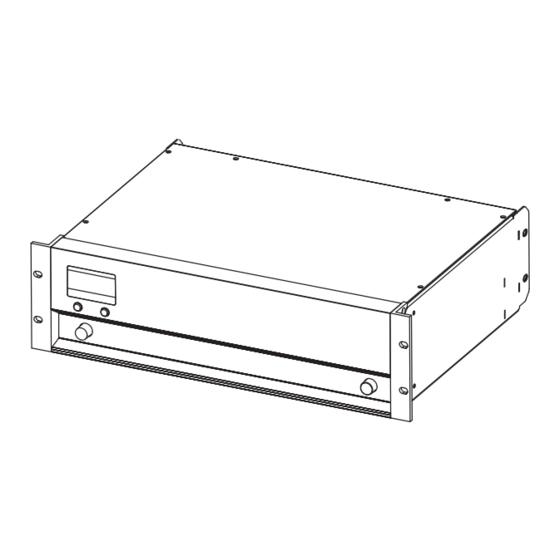
REMOTE and SERVICE interfaces, all connectors and status indicators. The D12 is housed in a 19" x 353 mm (13.9") 3 rack unit enclosure made from stainless steel with an extruded aluminium front panel. 3.2. D12 block diagram... -
Page 8: Digital Signal Processing
0.3 msec. into the signal path. If two identical loudspeakers are driven by different controllers the respective delays of the units used have to be considered (D12 = 0.3 msec., E-PAC = 1.0 msec. and A1/P1200A no delay). The D12 effectively positions its respective loudspeaker at a distance of 24 cm (0.79 ft) in front of a loudspeaker... -
Page 9: D12 Power Amplifiers
3.4. D12 power amplifiers The two power amplifiers fitted to the D12 can deliver 2 x 750 W continuous sine wave power into an 8 ohms load, increasing to 2 x 1200 W continuous sine wave power into a 4 ohms load. These maximum output ratings measured with sine wave are valid for minutes only until the unit will switch into thermal protect. -
Page 10: Power Supply
265 – 400 V Overvoltage Tab. 2: Voltage ranges 115/230 V To prevent the D12 from cycling on and off with fluctuating mains power supply voltages, the switching thresholds are delayed and about 4% apart from the border of the voltage range (hysteresis). -
Page 11: Inrush Current Limiter
The fan speed is consequently reduced during quieter passages preventing background noise interference. If the D12 heats up a "Temp. Warning" is given out and the fan will give full cooling power permanently. For further information please refer to section 6.1. Installation on page 3.8. -
Page 12: Controls And Indicators
The power consumption is very low (2 W typical). - ON: the D12 is switched on. Via remote or the MUTE A or B switch POWER the D12 can be switched to standby mode. To indicate standby mode the display remains active. -
Page 13: Level/Push Menu (Digital Rotary Encoder) [3]
Display and network remain functional, the display illumination is switched off after 10 seconds. Pressing the MUTE A or B switch powers on the D12 ready for use. The D12 may also be powered back on by remote control from standby mode. -
Page 14: Indicators
⇒ ⇒ ⇒ ⇒ Overload: either the input signal level is too high, gain reduction exceeds 12 dB or the D12 is trying to deliver too high an output current. If in doubt reduce the input gain at the D12 level control. If... -
Page 15: Connections
DO NOT OPEN RISK OF FIRE - REPLACE FUSE AS MARKED appropriate mains lead is supplied. FUSE T10A H / 250 V Two RJ45 [10] connectors are also provided for the D12 REMOTE FUSE T10A H / 250 V functions. MAINS SUPPLY... -
Page 16: Remote [10]
5.1.3. REMOTE [10] 1..8 1..8 Pin 1 n.c. The D12 is fitted with a 2-wire serial remote control interface, (2 x Pin 2 n.c. RJ 45) carrying both the RIB and CAN-Bus signals. All pins of both Pin 3 n.c. -
Page 17: Connector Panel (I/O Panel)
(AES/EBU) Power fail (Bypass) LINK output. Fig. 15: D12 Digital INPUT and LINK 5.2.3. OUT A/B [15 (a/b/c)] The D12 amplifier is supplied with EP5, NL4 or NL8 output connectors OUT A OUT A OUT A as an option. The pin assignment for the loudspeaker output connectors is... -
Page 18: Dual Channel Mode
5.2.4.1. Dual channel mode In "Dual channel mode" the D12 acts as an two channel amplifier – OUT A stereo amplifier. The amplifier channels are connected to their SenseDrive INPUT A AMP A respective output connectors (AMP Ch A to OUT A and AMP Ch B to... -
Page 19: 2-Way Active Mode - Single Input
The "2-Way Active mode" is dedicated to the d&b active systems OUT B 2-Way AMP B F1222, M2 and C3 as well as for M4 and MAX/MAX12 when driven actively. Applicable loudspeaker setups: Fig. 19: D12 Input/Output routing 2-Way Active mode J-Series with standard input routing C3/Ci3 M4 active F1222 MAX active In "2-Way Active mode"... -
Page 20: Loudspeaker Pin Assignments And Equivalents
2– n.c. n.c. n.c. SnsDrv LF SnsDrv LF SnsDrv Front 3– 3– 3– MF/HF+ LF+ Rear 4– 4– 4– HF– MF/HF– LF– Rear Fig. 20: Loudspeaker pin assignments and equivalents D12 Amplifier, Hardware manual (4.4 EN) Page 20 of 28... -
Page 21: Installation And Operation
We advise frequent cleaning of the fan filter to ensure good airflow through the unit. If the filter is visibly dirty, then it should be cleaned or replaced – see Fig. 22. Never operate the D12 without a filter. Dust deposits, especially combined with damp conditions, could cause the amplifier to malfunction. -
Page 22: Operating Conditions
The table gives power figures for various types of signal waveforms. They were measured on a D12 driving a 4 ohm load (both channels) to the clipping point of both channels using a sine wave burst signal of 24 dBu with a variable duty cycle. The mains power supply used for the measurements supplied an ideal sine wave with 230 V/50 –... -
Page 23: Mains Supply
When using the D12 at its upper temperature limit of 45 °C (113 °F), the maximum continuous output power is 500 watts total or 250 watts per channel. Again referring to section 6.2.1 - (Tab. 7) - the unit will work properly with e.g. -
Page 24: Technical Specifications
(refresh) Power Fail Relay (Bypass) OUT A/B......................EP5 / NL4 / NL8 dependent on the loudspeaker input version or type REMOTE......................2 x RJ 45 parallel SERVICE......................D-SUB-9 female D12 Amplifier, Hardware manual (4.4 EN) Page 24 of 28... - Page 25 Humidity (rel.), average....................70 % Dimensions and weight Height x width x depth..............3 RU x 19" x 353 mm ........................3 RU x 19" x 13.9 " Weight......................13 kg / 28.7 lb D12 Amplifier, Hardware manual (4.4 EN) Page 25 of 28...
-
Page 26: Technical Drawings
Fig. 24: D12 front view Fig. 25: D12 rear view MUTE LEVEL PUSH MENU POWER 483 [19.00"] 338 [13.31"] 443 [17.44"] 5 [0.20" ] Fig. 26: D12 enclosure dimensions in mm [inch] OUT A LINK INPUT LINK INPUT OUT A LINK INPUT OUT A... -
Page 27: Manufacturer's Declarations
- D12, Z2600.000/001 - D12, Z2600.300/301 manufactured by d&b audiotechnik GmbH. All products of type D12 starting from variant Z2600.000 are included, provided they correspond to the original technical version and have not been subject to any later design or electromechanical modifications. - Page 28 d&b audiotechnik GmbH, Eugen-Adolff-Str. 134, D-71522 Backnang, Germany, Phone +49-7191-9669-0, Fax +49-7191-95 00 00_______...
Need help?
Do you have a question about the D12 and is the answer not in the manual?
Questions and answers