Table of Contents

Subscribe to Our Youtube Channel
Related Manuals for d&b audiotechnik D6


Summary of Contents for d&b audiotechnik D6
- Page 1 D6 Amplifier Hardware manual (1.9 EN)
- Page 2 WARNING! Dangerous voltage! General Information D6 Amplifier Hardware manual Version 1.9 EN, 02/2014, D2017.EN.01 Copyright © 2014 by d&b audiotechnik GmbH; all rights reserved. Keep this manual with the product or in a safe place so that it is available for future reference.
-
Page 3: Table Of Contents
Contents 1. Introduction..............4 1.1. Intended use....................4 1.2. Scope of supply..................4 1.3. Maintenance/Service................5 2. D6 Amplifier..............6 2.1. D6 based systems..................6 2.2. Block diagram....................6 2.3. Power supply....................7 2.3.1. Inrush current limiter..............7 2.3.2. Mains voltage monitoring............7 2.4. Fan.........................7 2.5. D6 power amplifiers.................7 2.6. Digital signal processing................7 2.7. -
Page 4: Introduction
This manual describes the facilities and basic functions of the hardware of the D6 amplifier. A detailed description of the D6 software (firmware) menu structure and access is given in the D6 Software manual, which is also provided with the D6. -
Page 5: Maintenance/Service
The unit incorporates a lithium battery which may cause danger of explosion if not replaced correctly. - Refer replacement only to qualified service personnel authorized by d&b audiotechnik. - Only replace with the same type of battery. D6 Amplifier, Hardware manual (1.9 EN) Page 5 of 24... -
Page 6: D6 Amplifier
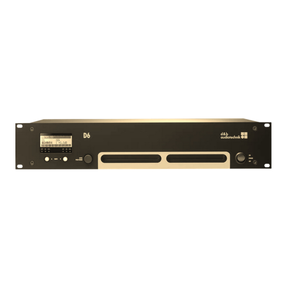
Each unit can be given a unique Device Name to simplify identification and a password protected LOCK function is also incorporated to inhibit unauthorized set up changes. The D6 is housed in a 19" x 351 mm (13.8") 2 rack unit enclosure made from steel. 2.2. -
Page 7: Power Supply
The D6 accepts mains voltages of up to 400 VAC without damage to the unit. -
Page 8: Controls And Indicators
A or B. The channel is unmuted by briefly pressing the corresponding MUTE switch. - A longer press (approx. 1.5 s) of MUTE A or B places the D6 in Standby mode. Briefly pressing the MUTE A or B switch again powers on the D6 ready for use. -
Page 9: Level/Push Menu
Display and network remain functional, the display illumination will be switched off after 10 s. Note: When the D6 is set to STANDBY (or the mains power is turned off) the movement of the loudspeaker cones in the cabinets connected is no longer damped by the power amplifier output. -
Page 10: Indicators
- when the analog input signal fed to the D6 analog inputs exceeds –30 dBu. - when the D6 digital input is locked to 48 or 96 kHz and the digital signal exceeds –57 dBFS (FS = Full Scale). 3.2.3. GR LED The GR LED [6] (Gain Reduction) illuminates yellow depending on the input signal. -
Page 11: Connections
Mains connector WARNING! Potential risk of electric shock. The D6 is a protective class 1 unit. A missing earth (ground) contact may lead to dangerous voltages in the housing and controls, and may lead to electric shock. - Connect the unit to mains voltage supplies with protective earth only. -
Page 12: Signal Inputs And Link Outputs
In this situation, the digital input Digital LINK Digital INPUT signal bypasses the analog buffer amplifier and is routed directly to the (AES/EBU) Power fail (Bypass) LINK output. Fig. 5: Digital INPUT Bypass D6 Amplifier, Hardware manual (1.9 EN) Page 12 of 24... -
Page 13: Loudspeaker Output Connectors - Out A/B
- Never connect an amplifier output pin to any other input or output connector pin or protective earth (ground). The D6 amplifier is supplied with NL4 output connectors [13]. Pins 1+/2+ and 1 /2— are wired in parallel and carry signal. -
Page 14: Remote Interface
4.4. REMOTE interface The D6 is fitted with a 2-wire serial remote control interface, (2 x RJ 45 [14]) carrying CAN-Bus signals. All pins of both connectors are wired in parallel allowing either to be used as the input or output. Where remote control networking conforms to a "Bus or Ring topology"... -
Page 15: Installation And Operation
Cooling Thermal conditions are a vital factor ensuring operational safety of the power amplifier. The D6 amplifier has an internal fan that draws cool air into the housing from the rear. It expels heated air through the vents on the front panel. -
Page 16: Operation
The table gives power figures for various types of signal waveforms. They were measured on a D6 driving a 4 ohm load (both channels) to the clipping point of both channels using a sine wave burst signal of 24 dBu with a variable duty cycle. -
Page 17: Mains Supply
(113° F), the maximum continuous output power is 340 watts total or 170 watts per channel. Again referring to section 5.2.1 - Tab. 4 - "D6 Power balance" - the unit will work properly with e.g. 150 watts total when either - running 4 ohms loads when the signal has a CF of 4.0... -
Page 18: Technical Specifications
Synchronization.........Word-Sync: PLL-locked to source (slave mode) LINK DIGITAL (Output)................XLR 3-pol. male ......................electronically balanced ......................analog signal buffering .......................power fail relay (Bypass) ............Pin assignment: 1 = GND, 2 = Signal, 3 = Signal D6 Amplifier, Hardware manual (1.9 EN) Page 18 of 24... - Page 19 Operating range (min./nom./max.)........85/115/130 V, 50 / 60 Hz low range ....................170/230/266 V, 50 / 60 Hz high range Mains fuse................2 x 8 A Time lag (T), internal 5 x 20 mm, high breaking capacity D6 Amplifier, Hardware manual (1.9 EN) Page 19 of 24...
-
Page 20: Dimensions
Height x width x depth..............2 RU x 19" x 351 mm .........................2 RU x 19" x 13.8" Weight......................8 kg / 17.6 lb 6.1. Dimensions 483 [19.00"] 338 [13.31"] 443 [17.44"] Fig. 8: Dimensions in mm [inch] D6 Amplifier, Hardware manual (1.9 EN) Page 20 of 24... -
Page 21: Manufacturer's Declarations
- D6 Amplifier, Z2700 manufactured by d&b audiotechnik GmbH. All products of type D6 starting from variant Z2700.000 are included, provided they correspond to the original technical version and have not been subject to any later design or electromechanical modifications. - Page 22 D6 Amplifier, Hardware manual (1.9 EN) Page 22 of 24...
- Page 23 D6 Amplifier, Hardware manual (1.9 EN) Page 23 of 24...
- Page 24 d&b audiotechnik GmbH, Eugen-Adolff-Str. 134, D-71522 Backnang, Germany, Phone +49-7191-9669-0, Fax +49-7191-95 00 00_______...
Need help?
Do you have a question about the D6 and is the answer not in the manual?
Questions and answers