Table of Contents
Advertisement
Quick Links
Advertisement
Table of Contents

Subscribe to Our Youtube Channel
Related Manuals for d&b audiotechnik D40


Summary of Contents for d&b audiotechnik D40
- Page 1 Reference manual 1.5 en...
- Page 2 Technical specifications: A/D conversion details added. Refer to: Þ "Digital Signal Processing" on page 7. General information D40 Reference manual Version: 1.5 en, 08/2023, D2038.EN .01 Copyright © 2023 by d&b audiotechnik GmbH & Co. KG; all rights reserved. Keep this document with the product or in a safe place so that it is available for future reference.
- Page 3 9. Unplug this apparatus during lightning storms or when unused for long periods of time. d&b D40 Reference manual 1.5 en...
-
Page 4: Table Of Contents
7.2 Configuration switches - Filter_1, _2, _3........ 43 7.3 Level..................43 7.4 EQ - Equalizer ................. 43 7.5 DLY - Delay................46 7.6 Input routing................47 7.7 System check/LM..............48 7.7.1 System check................. 48 7.7.2 Load monitoring (LM)............49 d&b D40 Reference manual 1.5 en... -
Page 5: Intended Use
Intended use Intended use The d&b D40 amplifier is designed for mobile applications and is intended to be used with applicable d&b loudspeakers. A "LINEAR" setup is available allowing the amplifier to be used as a linear power amplifier. Note: d&b audiotechnik will accept no liability for any damages to third-party loudspeakers when operated with d&b... -
Page 6: Scope Of Supply
3-pin Denmark 3-pin South Africa 3-pin Argentina 3-pin Brazil 3-pin India SEV 1011 Afsnit 107-2-D1 SANS 164-1 IRAM 2073 NBR 14136 IS 1293 *Mains plug types and associated standards (Similar illustrations, not in scale) d&b D40 Reference manual 1.5 en... -
Page 7: Technical Specifications
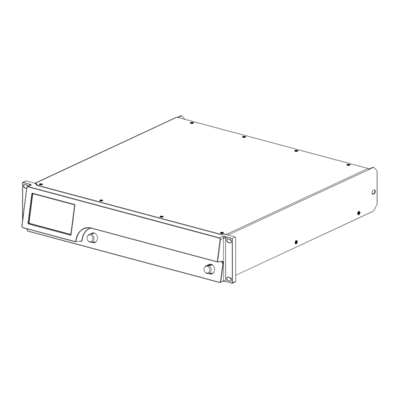
THD+N (unweighted, 20 – 20 kHz) 4 x 250 W/8 ohms < –86 dB/0.005 % 4 x 250 W/4 ohms < –83 dB/0.007 % Crosstalk (20 – 20 kHz) < –70 dBr 4 x 250 W into 8/4 Ω d&b D40 Reference manual 1.5 en... - Page 8 Rack mounted, measured on axis, 1 m (3.3 ft) to front panel, A-weighting. Height x width x depth 2 RU x 19" x 465 mm (18.3") Weight 13.8 kg/30.4 lb Min./Max. RPM 30/50 dB(A) Ambient temperature 23 °C/73.4 °F D40 enclosure dimensions in mm [inch] d&b D40 Reference manual 1.5 en...
- Page 9 Duration of max. output 4 ohms 1 x 2400 W 110 ms 8 ohms 1 x 2000 W 2000 ms 4 ohms 4 x 2400 W 5 ms 8 ohms 4 x 2000 W 4 ms d&b D40 Reference manual 1.5 en...
-
Page 10: Current/Power Draw And Thermal Dissipation
1200 1706 Noise CF 9 dB 11.6 0.98 2550 2000 1876 0.97 1800 1300 1706 Noise CF 6 dB 0.99 2900 2300 2047 0.98 1950 1400 1876 Sine wave max. 1 s 16.6 16.5 d&b D40 Reference manual 1.5 en... - Page 11 Noise CF 9 dB 18.8 0.98 2100 1600 1706 16.6 0.98 1900 1300 2047 Noise CF 6 dB 19.7 0.99 2250 1650 2047 17.7 0.98 2000 1400 2047 Sine wave max. 1 s 25.2 27.7 d&b D40 Reference manual 1.5 en...
- Page 12 Noise CF 9 dB 21.2 0.98 2000 1450 1876 20.8 0.98 1950 1300 2218 Noise CF 6 dB 21.0 0.99 2000 1450 1876 21.1 0.99 2000 1350 2218 Sine wave max. 1 s 30.3 32.7 d&b D40 Reference manual 1.5 en...
-
Page 13: Overview
4.3" / 480 x 272 pixels. indicators" on page 19, following Rotary encoder SCROLL/EDIT. Þ Chapter 5.3.1 "Mains power Refer to Þ Chapter 5.3 "Controls and switch" on page 19. indicators" on page 19 and . d&b D40 Reference manual 1.5 en... -
Page 14: Startup
▪ Do not combine the amplifiers with D6 or D12 amplifiers in one rack. ▪ Do not rack up the amplifiers together with other devices producing additional heat with opposing airflow. d&b D40 Reference manual 1.5 en... -
Page 15: Connections
100 to 240 V A C, ~50/60 Hz, 1800 W. ® A powerCON TRUE 1 TOP mains connector socket [1] is fitted on the rear panel and an appropriate power cord [1.1] is supplied. d&b D40 Reference manual 1.5 en... -
Page 16: Audio Input And Output Connectors
110 ohms, transformer balanced Sampling frequency 44.1 | 48 | 96 | 192 kHz Word length 16 - 24 bit OUT (D1/2 - D3/4) 3-pin XLR male electronically balanced analog signal buffering (refresh) Power Fail Relay (Bypass) d&b D40 Reference manual 1.5 en... -
Page 17: Speaker Outputs
Dual Channel - Mix TOP/SUB A/B - C/D A/B MIX - C/D MIX A/B - C/D MIX or... or... 2-Way Active - 2-Way Active Dual Channel - 2-Way Active 2-WAY - 2-WAY A/B - 2-WAY d&b D40 Reference manual 1.5 en... -
Page 18: Network Connections (Pri/Sec)
Illuminates permanently when the device is connected to an active network and flashes as long as a data stream is transmitted. Yellow ▪ Is off when the speed is 100 Mbit/s. ▪ Illuminates permanently when the speed is 1 Gbit/s. d&b D40 Reference manual 1.5 en... -
Page 19: Controls And Indicators
480 x 272 pixels and an additional digital rotary encoder [7]. The resistive touchscreen responds to pressure and therefore can be operated by a fingertip, even when wearing gloves or by an appropriate stylus tip (pen). d&b D40 Reference manual 1.5 en... -
Page 20: Operating Concept
In addition, the Home screen gives direct access to the Network subscreen. The Home screen can be accessed from any screen or menu at any level using the Home button ( ). Home screen access chart Hierarchy level d&b D40 Reference manual 1.5 en... - Page 21 Position cursor to the relevant item. ▪ Access the selected item or function element by pushing the encoder. ▪ Enter/edit values by turning the encoder. ▪ Confirm entered/changed values or leave Edit mode by pushing the encoder. d&b D40 Reference manual 1.5 en...
-
Page 22: Standby Mode
Mute function instead of Standby. However, the Standby mode can be useful with mid/high systems as it removes any residual noise from the system. d&b D40 Reference manual 1.5 en... -
Page 23: Mute Functions
↳ A dialog appears allowing you to either select the Back button ( - cancel), «Mute all» or «Standby». 2. Select «Mute all». 3. To unmute the channels, use the individual Channel mute buttons. d&b D40 Reference manual 1.5 en... -
Page 24: Device Setup
Device setup Device setup Device setup access chart d&b D40 Reference manual 1.5 en... -
Page 25: Device Name
Input configuration The «Input» tab offers the complete input management in one place where you can configure dedicated input settings, such as: Þ Input monitoring (Mon) Þ Input gain (Gain) Þ Fallback Þ Override d&b D40 Reference manual 1.5 en... -
Page 26: Input Management
You can select and set every channel individually. See the table above for all available channel modes. The error status is also indicated on the «Home» screen. A corresponding message (Input monitoring fault) will be issued. d&b D40 Reference manual 1.5 en... -
Page 27: Input Gain
The on/off status is indicated by a change in color of the button from gray to blue or vice versa. Clear All gain settings are reset to factory default (0 dB) while the function remains activated. d&b D40 Reference manual 1.5 en... -
Page 28: Fallback
The override function is available for input channels. The override function allows to set an input channel as a major signal path. When the function is activated, the input channel has the highest priority for general messages or emergency services. d&b D40 Reference manual 1.5 en... - Page 29 Attack time, adjustable from 0.01 sec. to 1 sec. in 0.01 sec. increments. Hold Hold time, adjustable from 0 sec. to 10 sec. in 0.1 sec. increments. Release Release time, adjustable from 0 sec. to 10 sec. in 0.1 sec. increments. d&b D40 Reference manual 1.5 en...
-
Page 30: Output
On the bottom left of the Output screen, the «Speaker» navigation button provides direct access to the Speaker setup screen. 6.4 Network Select the «Network» tab to assign remote settings for Ethernet remote control. d&b D40 Reference manual 1.5 en... -
Page 31: Ip Settings
«Network» screen keeping the previous entry. Set gateway When this button is selected, the gateway to default address is derived from the IP address and IP mask settings. d&b D40 Reference manual 1.5 en... -
Page 32: Remote Id
Selecting the «More» tab provides further subscreens such as: ▪ Preferences ▪ Info ▪ Levels ▪ Mains current limiter ▪ ... 6.5.1 Preferences Select «Preferences» to open the corresponding subscreen with the «Display» tab being active. d&b D40 Reference manual 1.5 en... -
Page 33: Display
Password protection to prevent operation by unauthorized persons. Screen Select «Screen» to allow two different settings for the screen when the device is locked. Home screen Switches to the Home screen. Levels Switches to the Levels screen. d&b D40 Reference manual 1.5 en... - Page 34 3. Release the encoder and briefly press the encoder again within 2 sec. ↳ Short confirmation beep. The device will boot up and will switch to the home screen. A corresponding message will be issued: d&b D40 Reference manual 1.5 en...
-
Page 35: Preferences/More
3. Release the encoder and briefly press the encoder again within 2 sec. ↳ Short confirmation beep. The device will boot up and will switch to the Home screen. A corresponding message will be issued: d&b D40 Reference manual 1.5 en... -
Page 36: Info
Indicates whether the input signal (ISP) as well as the amplifier output signal (OSP) of the individual channel are present. GR/OVL Indicates whether gain reduction (GR) of the respective channel is active or the respective channel is overloaded (OVL). d&b D40 Reference manual 1.5 en... -
Page 37: Mains Current Limiter (Mcl)
6.5.4 Mains current limiter (MCL) Selecting «Mains current limiter» opens the corresponding subscreen. The D40 features a power limiter which serves to limit the mains current draw whenever the mains current draw threatens to trigger the circuit breaker. Limiting is done by reducing the sound levels evenly on all channels. -
Page 38: Energy Saving
Time to Time (countdown), adjustable from 1 min. to Standby 24 h in 1 min. increments. Threshold Threshold for the AutoStandby and AutoWakeup functions, adjustable from –140 dBFS to 0 dBFS in 1 dB increments. d&b D40 Reference manual 1.5 en... -
Page 39: Amppresets
AmpPresets screen. ▪ Selecting the Back button ( ) on the top left cancels any entry and switches back to the AmpPresets screen keeping the previous entry. d&b D40 Reference manual 1.5 en... -
Page 40: Event Log
Back button ( ). 6.5.7 Event log The event log stores a maximum of 10000 records. Once the maximum number of records is reached, the system starts deleting the first ones. d&b D40 Reference manual 1.5 en... -
Page 41: Channel Setup
Channel setup Channel setup Channel setup access chart d&b D40 Reference manual 1.5 en... -
Page 42: Channel Name
Tapping the Back button ( ) on the top left cancels any entry and switches back to the Channel setup screen keeping the previous entry. d&b D40 Reference manual 1.5 en... -
Page 43: Configuration Switches - Filter_1
EQ) within the signal chain. The equalizer provides two independent and user definable 16- band equalizers (2 x 16 minimum phase biquad IIR filters, full parametric) and is split into two layers: Þ EQ overview, Þ EQ layer/curve. d&b D40 Reference manual 1.5 en... - Page 44 1. Select the channel EQ you want to copy. 2. Select «Copy». ↳ The «Paste» button becomes accessible. 3. Select the channel to which you want to paste the EQ settings. 4. Select «Paste». Step 1 Step 2 Step 3 Step 4 d&b D40 Reference manual 1.5 en...
- Page 45 Q (and Gain corresponding (Parametric EQ) bandwidth - BW) Notch Q (and corresponding bandwidth - BW) HiShlv Slope Gain LoShlv Slope Gain Asym FRQ 1 Slope 1 Gain FRQ 2 Slope 2 (Asymmetric filter) d&b D40 Reference manual 1.5 en...
-
Page 46: Dly - Delay
0.1 ms or a corresponding value depending on the units selected. Unit Enables selection of the delay units, either milliseconds [ms], meters [m], feet [ft] or seconds [s]. A change in the units will be applied to all channels. d&b D40 Reference manual 1.5 en... -
Page 47: Input Routing
A simple example is shown in the graphic opposite. The stream labels are stated in inverted commas. The corresponding labels and their locations on the screen are listed in the table below. Out 1/2 Main R@FoH DS10 Stage R Front - Output 1 d&b D40 Reference manual 1.5 en... -
Page 48: System Check/Lm
To verify the correct connection of cabinets and amplifiers, the calibration result can be compared with the typical impedance values for d&b loudspeakers. For this purpose, please refer to the d&b R1 Help (Þ within R1 press F1). d&b D40 Reference manual 1.5 en... -
Page 49: Load Monitoring (Lm)
The maximum time it takes the system to detect a loudspeaker malfunction. The intervals of the pilot signal are derived from this parameter. The time can be set in a range from 40 to 1000 sec. in 40 sec. detents. d&b D40 Reference manual 1.5 en... -
Page 50: Speaker
The starting point, however, is the setup currently loaded. Selecting «OK» adjacent to the «Speaker» selection field confirms the configuration and the selected setup will be activated. d&b D40 Reference manual 1.5 en... - Page 51 LoadMatch subscreen which is described in Þ Chapter 7.8.2 "LoadMatch" on page 53. Note: LoadMatch does not apply to all loudspeakers. When the function is not applicable, this button is not functional. d&b D40 Reference manual 1.5 en...
-
Page 52: Arrayprocessing
On the Home screen, the On/Off status and the setting of the HF Trim option is indicated by the entry «HFT[n]» on the «Channel view» button of the corresponding channel strip, as shown in the graphic opposite. d&b D40 Reference manual 1.5 en... -
Page 53: Loadmatch
«Cable impedance» information field underneath. Maximum gain reached The message «Maximum gain reached» is displayed when the maximum compensation that the specific loudspeaker setup allows as a balance between sonic accuracy and headroom has been reached. d&b D40 Reference manual 1.5 en... -
Page 54: Linear Setup
Channel setup 7.8.3 LINEAR setup In addition to the loudspeaker specific setups, a LINEAR setup is also available allowing the D40 to be used as a linear power amplifier. Note: CUT in LINEAR setup: ▪ Butterworth 2nd order (12 dB/oct.) ▪... -
Page 55: Frequency Generator
Þ To confirm the set frequency, press the encoder. On the Home screen, the On/Off status of the generator is indicated by the entry «FG» on the Channel view button of the corresponding channel strip, as shown in the graphic opposite. d&b D40 Reference manual 1.5 en... -
Page 56: Web Remote Interface
«Web Remote», «Event log», «Commands» and «Service» tabs. Web Remote tab The «Web Remote» tab shows the actual screen of the connected amplifier. All screens and screen items can be accessed by simply clicking the relevant item. d&b D40 Reference manual 1.5 en... - Page 57 ↳ An input mask will be displayed which allows you to enter the desired data by clicking the respective characters and/or numbers. 6. Confirm your entry by clicking the corresponding «OK» button. d&b D40 Reference manual 1.5 en...
- Page 58 3. Select «Save» to store the Event log data locally. ↳ Your web browser will display the corresponding dialog and the file will be saved as to the local Event.log download directory you have specified in the download settings of your browser. d&b D40 Reference manual 1.5 en...
- Page 59 Logout To exit the «Service» tab functions, click the «Logout» button at the top. d&b D40 Reference manual 1.5 en...
- Page 60 Web Remote interface Licenses and Copyright Selecting the d&b logo at the top left opens the «Licenses and Copyright» information page. d&b D40 Reference manual 1.5 en...
-
Page 61: Operation (Hardware References)
100 - 127 V A C Auxiliary Power Supply The Auxiliary Power Supply feeds the DSP section and the device control and operates within the range from 55 V A C 400 V A C d&b D40 Reference manual 1.5 en... -
Page 62: Mains Inrush Current Limiter
9.1.4 Mains inrush current limiter The Main Power Supply is started softly to limit inrush current. Up to two D40 may be powered up at the same time without triggering a line circuit breaker of 13-16 A (230 V) or 20 A (100-120 V) respectively. -
Page 63: Generator Operation/Ups Requirements
To operate the amplifier using a mains generator or uninterruptible power supply (UPS), observe the following: ▪ With the D40 amplifier the apparent power figure (VA value) is about the same as the effective power figure (W value). ▪ Use a generator or UPS that can deliver the maximum power required by the entire system. -
Page 64: Power Amplifiers
Operation (Hardware references) 9.2 Power amplifiers The power amplifiers fitted to the D40 utilize Class D technology similar to a switch mode power supply. Compared to the known linear amplifier concept (Class A, AB, G or H), Class D power amplifiers produce less heat and allow for a compact and light- weight design. -
Page 65: Service/Maintenance And Care
TFT screens. In this case, proceed as follows: 1. Spray on the soft cloth before wiping the screen. ↳ Never apply/spray directly on the screen as the liquid could penetrate the device. 2. Wipe the screen with moderate pressure. d&b D40 Reference manual 1.5 en... -
Page 66: Touchscreen Calibration
1. From the «Home» screen go to «Device» Þ «More» Þ «Preferences» Þ «Display». 2. On the bottom left, select «Touchscreen calibration». ↳ The calibration menu will be issued, guiding you through the calibration procedure. 3. Follow the on screen instructions respectively. d&b D40 Reference manual 1.5 en... -
Page 67: Possible Error Messages
%3.1dA, avg %3dV, err %04X) see Þ Chapter 9.1.3 Mains overvoltage Mains overvoltage Mains voltage too SMPS (avg %3dV, peak high for current range "Automatic mains %3dV, err %04X) range selection" on page 61 d&b D40 Reference manual 1.5 en... - Page 68 Amp. comm. error SMPA Communication communication error No keepalive for 1 disturbed or SMPA (error %04X) defect Temperature error %d Channel '%c' Critical amp. channel SMPA Insufficient cooling °C temperature error %d temperature °C (power %uW) d&b D40 Reference manual 1.5 en...
- Page 69 OCA remote error OCA remote error OCA remote error Speaker imp. fault Load Monitoring Speaker defect, cable impedance error Input fallback Input fallback (A1= Input Fallback Input Fallback was %d, A2=%d, D1=%d, activated D2=%d) d&b D40 Reference manual 1.5 en...
- Page 70 Input Monitoring Cabling AX (level %4.1ddBu, Fault threshold %4.1ddBu) 165-168 Input monitoring fault Input monitoring fault Input Monitoring Cabling, routing, DX (level Fault unlocked %4.1ddBFS, lock %d, DS data pri %d, DS data sec %d) d&b D40 Reference manual 1.5 en...
-
Page 71: Manufacturer's Declarations
As required by the GPL and LGPL licenses, we will send you a copy of the used source code on request. If you would like to obtain a copy, please contact us by mail to: software.support@dbaudio.com d&b D40 Reference manual 1.5 en... - Page 73 www.dbaudio.com...
Need help?
Do you have a question about the D40 and is the answer not in the manual?
Questions and answers