
Related Manuals for d&b audiotechnik E-PAC


Summary of Contents for d&b audiotechnik E-PAC
- Page 2 E-PAC Amplifier Hardware manual (1.2 EN)
- Page 3 Please refer to the information in the operating manual. WARNING! Dangerous voltage! General Information E-PAC Amplifier Hardware manual Version 1.2 EN, 02/2013, D2014.E.01 Copyright © 2013 by d&b audiotechnik GmbH; all rights reserved. Keep this manual with the product or in a safe place so that it is available for future reference.
-
Page 4: Table Of Contents
Contents 1. Safety precautions............4 1.1. Information regarding use of the E-PAC Amplifier......4 1.2. Service/Maintenance................4 2. Introduction..............5 2.1. Intended use....................5 2.2. Scope of supply..................5 3. E-PAC Amplifier..............6 3.1. E-PAC based systems................6 3.2. Block diagram....................6 3.3. Power supply....................7 3.4. Protective circuits..................7 3.5. Cooling......................8 3.6. -
Page 5: Safety Precautions
1. Safety precautions 1.1. Information regarding use of the E-PAC Amplifier The E-PAC is a protective class 1 unit. Make sure that the earth (ground) contact is attached when the unit is in operation. A missing earth (ground) contact may lead to dangerous voltages in the housing and controls and my lead to electric shock. -
Page 6: Introduction
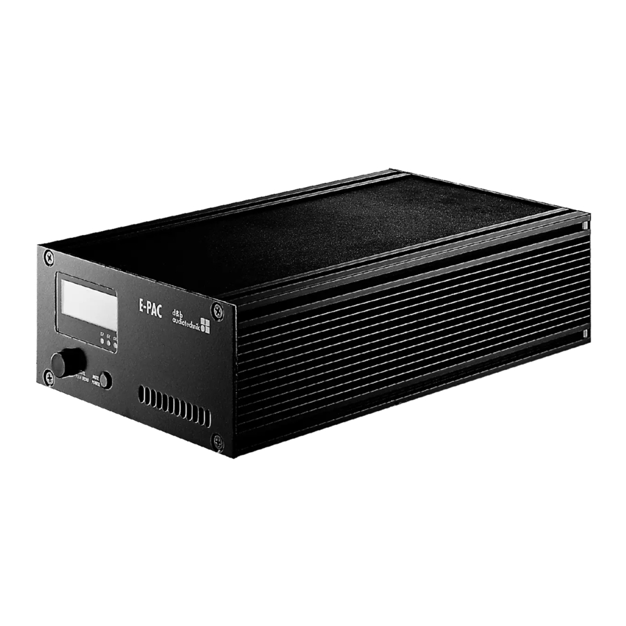
The E-PAC amplifier is a one channel power amplifier and controller unit. It is designed for use with the d&b fullrange loudspeakers (passive systems) and subwoofer systems. A linear mode is available allowing the E-PAC to be used as a linear power amplifier. 2.2. Scope of supply... -
Page 7: E-Pac Amplifier
The E-PAC is specifically designed for high impedance loads (200 W into 16 ohms, 300 W into 8 ohms). If low impedance (LO IMP) mode is selected the E-PAC can drive up to two 8 ohm or four 16 ohm loudspeakers, at reduced output (–6 dB). -
Page 8: Power Supply
2 A (peak) at 230 V and 4 A (peak) at 115 V. The nominal operating range of the E-PAC is between 85 V and 265 V (100 V –15% /230 V +15 %). Where voltages outside of this range... -
Page 9: Cooling
The aluminium enclosure acts as a heat sink for the E-PAC power amplifier; it is therefore convection-cooled. To prolong the life of components inside the E-PAC, a small fan located at the front of the E- PAC intakes cooling air through an opening in the rear panel. The quiet running fan is activated at two temperature thresholds. -
Page 10: Controls And Indicators
The power consumption is very low (2 W typical). Mains power switch on: the E-PAC is switched on. Via remote or the MUTE control the E- PAC can be switched to standby mode. To indicate standby mode the display remains active. -
Page 11: Level/Push Menu (Digital Rotary Encoder) [3]
When the E-PAC is set to STANDBY (or the mains power is turned off) IMPORTANT! the movement of the loudspeaker cones in the cabinets connected is no longer damped by the power amplifier output. This removal of the damping makes them susceptible to excitation by other loudspeakers in the surroundings. -
Page 12: Indicators
- While the green ISP-LED is lit » Overload: either the input signal level is too high or the E-PAC is trying to deliver too high an output current. If in doubt of the reason reduce the input gain at the E-PAC level control. -
Page 13: Connections
Only use a fuse of the correct type and nominal current value. Before restoring power to the E-PAC all cabling should be checked for faults. If in any doubt disconnect all signal and loudspeaker connections. E-PAC Amplifier, Hardware manual (1.2 EN) -
Page 14: Signal Inputs And Link Outputs
NL4 loudspeaker output (SPEAKER OUT). 5.3.1. INPUT [12] and LINK [13] The E-PAC signal input connector is a 3 pin female XLR. Below and wired in parallel is a 3 pin male XLR input link connector used to feed the input signal on to the next device in the system signal chain. -
Page 15: Remote Interface [14]
5.5. REMOTE interface [14] [11] [10] E-PAC Remote interfaces 5.5.1. REMOTE [10] The E-PAC is fitted with a two-wire serial remote control interface, (2 x 1..8 1..8 Pin 1 n.c. Pin 2 n.c. RJ 45) carrying both the RIB and CAN-Bus signals. All pins of both Pin 3 n.c. -
Page 16: Installation And Operation
6. Installation and operation 6.1. Installation A single E-PAC may be installed in a 9.5" equipment rack or a standard 19“ equipment rack or flightcase. A single E-PAC or a pair side-by-side may be installed in a standard 19" equipment rack or flightcase. E-PACs require two rack units and, including connectors, a minimum rack depth of 40 cm (16"), mounting ear to rack rear panel. -
Page 17: E-Pac Rack Mount Kits
- 16 x Allen screws [S], - 1 x Allen key [K] The solo rack mount kit Z2503 allows one E-PAC to be mounted in a 9.5“ equipment rack or flightcase. The solo rack mount kit (Z2503) includes the following parts:... -
Page 18: Dimensions
338 [13.31"] E-PAC LEVEL MUTE PUSH MENU POWER 483 [19.00"] 465 [18.30"] E-PAC E-PAC LEVEL MUTE LEVEL MUTE PUSH MENU POWER PUSH MENU POWER E-PAC enclosure dimensions in mm [inch] E-PAC Amplifier, Hardware manual (1.2 EN) Page 17 of 24... -
Page 19: Operation
Crestfactor 16 ohms 8 ohms 4 ohms (LO IMP) Maximum output power and power loss of E-PAC for different signal characteristics (Crest factors) at full level. E-PAC Amplifier, Hardware manual (1.2 EN) Page 18 of 24... - Page 20 [W] average output power [W] Power consumption and loss of E-PAC as a factor of output Average power consumption and loss of E-PAC as a factor of power (WRMS into 8 ohms) with pink noise signal...
-
Page 21: Technical Specifications
Mains inrush current limiter........2 A peak at 230 V, 4 A at 115 V Overvoltage protection..................up to 400 V Self resetting overtemperature protection..........75°C /167°F Output short and open circuit protection.............±20 A Speaker switch on delay................approx 2 sec. E-PAC Amplifier, Hardware manual (1.2 EN) Page 20 of 24... - Page 22 Weight......................4.7 kg / 10.4 lb Universal voltage range switched mode power supply with active power factor correction (PFC) Mains voltage rating..............85 – 265 V / 50 – 60 Hz Mains fuse.....................5A Time lag (T) E-PAC Amplifier, Hardware manual (1.2 EN) Page 21 of 24...
-
Page 23: Manufacturers Declarations
8. Manufacturers declarations 8.1. EU declaration of conformity (CE symbol) This declaration applies to the E-PAC power amplifier controller manufactured by d&b audiotechnik AG consisting of the amplifier unit. - E-PAC Z2510 all versions All production versions of type E-PAC starting from version Z2510.000.01 are included, provided they correspond to the original... - Page 25 d&b audiotechnik GmbH, Eugen-Adolff-Str. 134, D-71522 Backnang, Germany, Phone +49-7191-9669-0, Fax +49-7191-95 00 00_______...
Need help?
Do you have a question about the E-PAC and is the answer not in the manual?
Questions and answers