Advertisement
Quick Links
Download this manual
See also:
Instruction Manual
Quickstart Guide
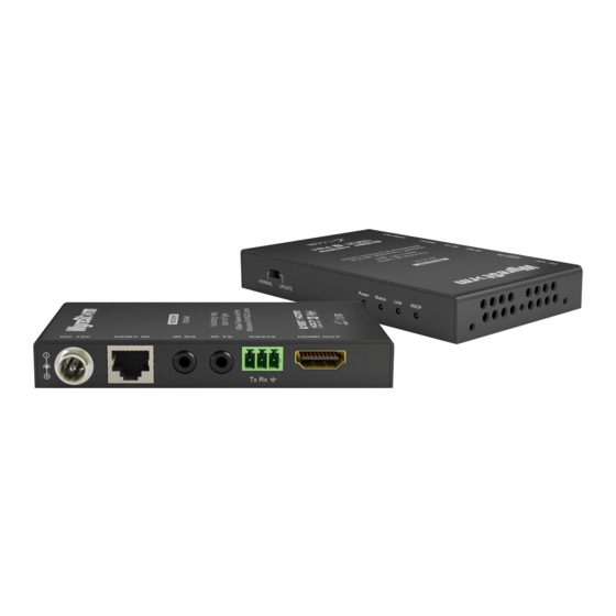
WyreStorm 4K HDBaseT Extender Set with 2-Way IR,
RS232 and PoH (4K: 35m/115ft - 1080p: 70m/230ft)
EX-35-4K
Before Installation
35m/115ft @ 4K and 70m/230ft @1080p video are maximum
recommended transmission distances for this model and
denotes perfect transmission conditions - including straight
cable runs with no electrical interference, bends, kinks, patch
panels or wall outlets. If any of the above is a factor in your
installation, transmission range may be affected – take care to
avoid where possible.
We strongly recommend using supplied mounting brackets to
secure the receiver to a flat surface behind/near the display
device. Sudden movement of these devices could lead to loss of
picture/sound if connections become loose or strained, resulting
in unnecessary service call-backs.
If unsure of positioning, IR sensors can be located on devices by
shining a flashlight onto the fascia of the device - the IR sensor
should be identifiable as a small round sensor behind the panel.
Consult your device manufacturer handbook if difficulties are
experienced.
Setup and Operation
1
Using quality HDMI cables, connect an HDMI source (such as
Blu-ray, games console, satellite/cable TV, media server etc.) to the
HDMI IN of the EX-35-4K Transmitter.
NOTE: Ensure source and display are 4K compatible if
attempting to transmit an UltraHD signal.
2
Connect a good quality, well-terminated Cat5e/6 cable of no more
than 35m/115ft for 4K or 70m/230ft for 1080p in length between
the HDBT OUT of the EX-35-4K Transmitter to the HDBT IN Input
of the EX-35-4K Receiver.
3
Connect the HDMI display device (LED/LCD display or projector) to
the HDMI OUT of the EX-35-4K Receiver
4
Connect the included 12v power supply to the EX-70-4K
Transmitter and power on. The one-way PoH function carries
power along the length of the cable to power the Receiver so no
mains power is required at display zones.
NOTE: Optional 12v power input is available on the Receiver
if required. For example, if the cable is too weak to carry the
power.
5
Check POWER, STATUS & LINK lights are illuminated on both units
to indicate successful connection, with a lit HDCP light illustrating
the presence of encryption within the signal. STATUS and HDCP
should be blinking. POWER and LINK are static lights.
NOTE: If daisy-chaining extenders, repeat process for all
EX-35-4K Transmitters and Receivers used.
Signal IR/RS232 Control Connection
6
For two-way IR control of connected sources and displays from
either location, first, connect IR transmitters to the IR TX ports of
the EX-35-4K Transmitter and EX-35-4K Receiver.
7
Firmly attach the IR emitter eye directly over the infrared receiving
sensors of the devices to be controlled (source at Transmitter
location, and display device at receiver location). Location of the
emitter eye on the device may need to be adjusted later to achieve
best IR performance.
8
Insert IR receivers into IR RX ports of the EX-35-4K Receiver and
EX-35-4K Transmitter.
9
At both display and source locations, position the IR receiver on or
near the device to be controlled, ensuring a clear line of sight to the
remote handset used to control it.
For linking with a control system, a WyreStorm IR Integration Cable
(CAB-IR-LINK) should be used to connect the IR RX port of the
EX-35-4K Transmitter and the control system.
For an RS232-based control system, RS232 cables should be
connected between RS232 ports of the EX-35-4K Transmitter and
control system, and RS232 ports of the EX-35-4K Receiver and the
display device to enable fully routed serial control between devices.
4K SOURCE DEVICE
7
4
8
6
Mains
power
2
8
6
7
9
1
EX-35-4K
Transmitter
NOTE: Although WyreStorm products are tested
with Cat5e, we recommend Cat6 due to increased
bandwidth and improved capacity for handling large
transmissions along a single cable.
EX-35-4K
Receiver
DISPLAY OUTPUT
3
Control
System
Advertisement

Related Manuals for Wyrestorm EX-35-4K


Summary of Contents for Wyrestorm EX-35-4K
-
Page 1: Before Installation
IR performance. EX-35-4K Insert IR receivers into IR RX ports of the EX-35-4K Receiver and EX-35-4K Transmitter. At both display and source locations, position the IR receiver on or near the device to be controlled, ensuring a clear line of sight to the remote handset used to control it. -
Page 2: Troubleshooting
Cat5e/6 Wiring Guide Cat5e/6 Cable Performance Guide EX-35-4K The quality of termination for every RJ45 100m is essential. Poor terminations leads to 32ft 65ft 98ft 131ft 164ft 197ft 230ft 262ft 295ft 328ft intermittent performance and longer install times. 4K Transmission...
Need help?
Do you have a question about the EX-35-4K and is the answer not in the manual?
Questions and answers