
Subscribe to Our Youtube Channel
Related Manuals for Palstar AT1500DT


Summary of Contents for Palstar AT1500DT
- Page 1 AT1500DT 1500 Watt Antenna Tuner Owner’s Manual © Copyright 2006 Palstar Inc. Printed in the U.S.A.
-
Page 2: Important Safeguards
This product should not be placed in a built-in left unattended and unused for long periods of installation such as a bookcase or rack unless time, unplug it from the wall outlet. 1-800-773-7931 WWW.PALSTAR.COM... - Page 3 An improper adjust- mation. ment may result in damage and will often e. Use jumper wire not smaller than No.6 require extensive work by a qualified AWG copper or equivalent, when a separate antenna grounding electrode is used. 1-800-773-7931 WWW.PALSTAR.COM...
-
Page 4: Table Of Contents
Important safeguards Table of Contents General Description Specifications Installation Unpacking Location Installation Procedures AT1500DT Schematic Rear Panel Connections 10 Front Panel Description Operating Your AT1500DT 12 Before Operating Tuning Notes Service and Warranty 1-800-773-7931 WWW.PALSTAR.COM... -
Page 5: General Description
General Description The Palstar AT1500DT Antenna The AT1500DT also features a Tuner is an American made im- precision roller inductor with a pedance matching network that steatite ceramic core. The inno- can provide unbalanced and vative differential capacitor de- balanced output. -
Page 6: Specifications
4:1 Ruthroff voltage type balun Dimensions 4.5”H x 12.6”W x 12”D (incl. terminals) Weight 12 lbs. Materials Chassis and top cover is 11 ga. (.090) aluminum that has been chem.-film treated in gold color. Front Panel powder-coated and epoxy screened. 1-800-773-7931 WWW.PALSTAR.COM... -
Page 7: Installation
Location plied jumper strap between the Select a location for the lower BALANCED OUTPUT and AT1500DT that allows the con- the END FED WIRE posts (see nectors to be free form any pos- pg 10). sible contact during operation to... -
Page 8: At1500Dt Schematic
AT1500DT Schematic MODEL AT1500DT DIFF-T TUNER 1-800-773-7931 WWW.PALSTAR.COM... - Page 9 BYPASS coaxial connector for PLEASE DO NOT REMOVE output to dummy load or third coax output. Bypasses tuner, but meter circuits are on if AC adap- tor is connected to jack located on rear panel. FIGURE 1 REAR PANEL CONNECTORS 1-800-773-7931 WWW.PALSTAR.COM...
-
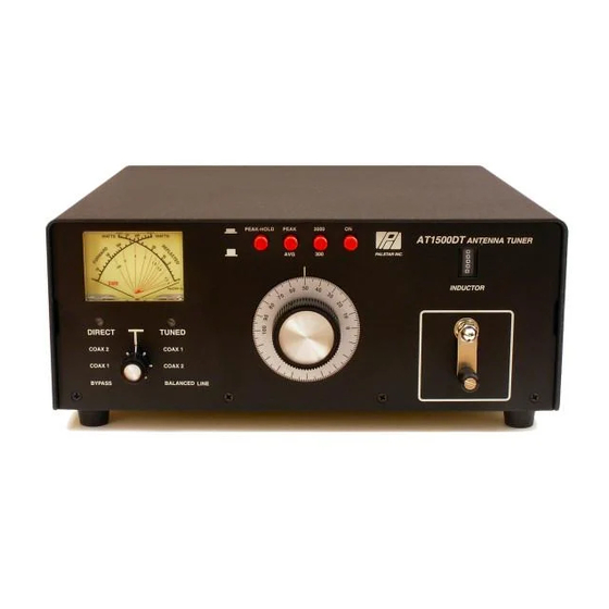
Page 10: Front Panel Description
Coupled to the crank handle nector through the tuner matching T cir- is a gear-driven precision mechanical cuit. counter. f. BALANCED OUT selects the balanced and End Fed Wire output connectors lo- cated after the impedance matching circuit. 1-800-773-7931 WWW.PALSTAR.COM... -
Page 11: Operating Your At1500Dt
6. Set the DIRECT/TUNED mode power setting (50-100 Watts). switch to BYPASS or the position WARNING: DO NOT OPERATE THE AT1500DT WITH THE COVER OFF. Tuning matching your antenna connection. To tune your antenna, the switch selection 1. - Page 12 10. When you have tuned your an- tenna to the best SWR, record the settings of the INPUT, ANTENNA and INDUCTANCE controls on the chart above for future reference. When you retune, use these settings as your starting point. 1-800-773-7931 WWW.PALSTAR.COM...
-
Page 13: Notes
4. Any time a new or different antenna is connected, it is necessary to repeat the tuning procedure for each antenna. 1-800-773-7931 WWW.PALSTAR.COM... -
Page 14: Service And Warranty
R30, and ZM30 and all other prod- the service. Package your radio prop- ucts for one (1) year from the erly. Palstar, Inc. is not responsible for date of delivery to the first buyer merchandise damaged in shipment. (the “Warranty Period”). Palstar, Inc’s... - Page 15 Palstar Incorporated 9676 N. Looney Rd., Piqua, OH 45356 USA Customer Service and Sales Telephone: 1-800-773-7931 Fax: 1-937-773-8003 Email: info@palstar.com...
Need help?
Do you have a question about the AT1500DT and is the answer not in the manual?
Questions and answers