Palstar AT5K Owner's Manual
3500 watt antenna tuner
Hide thumbs
Also See for AT5K:
- Owner's manual (10 pages) ,
- Owner's manual (20 pages) ,
- Technical manual (9 pages)

Related Manuals for Palstar AT5K


Summary of Contents for Palstar AT5K
- Page 1 AT5K 3500 Watt Antenna Tuner Owner’s Manual © Copyright 2006 Palstar Inc. Printed in the U.S.A. Rev. 1.1...
-
Page 2: Important Safeguards
This product should not be placed in a built-in left unattended and unused for long periods of installation such as a bookcase or rack unless time, unplug it from the wall outlet. 1-800-773-7931 WWW.PALSTAR.COM... - Page 3 An improper adjust- mation. ment may result in damage and will often e. Use jumper wire not smaller than No.6 require extensive work by a qualified AWG copper or equivalent, when a separate antenna grounding electrode is used. 1-800-773-7931 WWW.PALSTAR.COM...
-
Page 4: Table Of Contents
Table of Contents Thank you for purchasing a Please carefully read the Palstar AT5K Antenna Tuner. Owner’s Manual in order to take This antenna tuner has been advantage of the many interest- designed and manufactured to ing features that will provide... -
Page 5: General Description
3500 watts (single tone Integrated into the AT5K is a continuous) and 5000 watts frequency-compensated lighted- PEP at certain Z ranges (p.14). dial dual-movement SWR me- ter. -
Page 6: Specifications
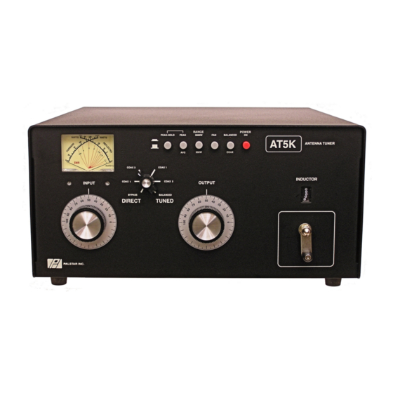
1:1 current type Balun at input-Ferrite Dimensions 8”H x 16”W x 18”D (incl. terminals) Weight 25 lbs. Materials Chassis, brackets, and top cover are gold chem-film coated aluminum (.090) & powder coated. Front Panel Front panel is matte powder coated and screened. 1-800-773-7931 WWW.PALSTAR.COM... -
Page 7: Installation
Location Select a location for the AT5K For a balanced feed antenna that allows the connectors to be connect a balanced feed line to free from any possible contact... -
Page 8: At5K Schematic
AT5K Schematic 1-800-773-7931 WWW.PALSTAR.COM... - Page 9 BYPASS coaxial connector for and fan. output to dummy load or third coax output. Bypasses tuner, but meter circuits are on if AC adap- tor is connected to jack located on rear panel. FIGURE 1 REAR PANEL CONNECTORS 1-800-773-7931 WWW.PALSTAR.COM...
-
Page 10: Front Panel Description
For balanced antennas, the balanced coax switch must be IN. nated also this provides power to the relay 10. INPUT Continuously adjustable input and the peak and peak/hold circuits. capacitor. Min. capacitance = 0. Max = 100. 7. INDUCTOR 28 H continuously vari- 1-800-773-7931 WWW.PALSTAR.COM... -
Page 11: Operating Your At5K
COAX) with the pushbutton on the power setting (50-150 Watts). front panel. Note: BALANCED shows WARNING: DO NOT OPERATE THE AT5K WITH THE COVER OFF. Tuning red LED. 5. Set the POWER RANGE switch to 1. -
Page 12: Notes
Operating Your AT5K cont’d 7. Key your transmitter and adjust the to use high power and the use of an RF power level for a reading of 100-150 analyzer would be advisable (e.g. the watts on the FORWARD scale. Adjust... - Page 13 160M — 3500 watts 80M - 15M—3500 watts 10M — 1500 watts (29.5 Mhz max) IF IN ANY DOUBT ABOUT YOUR ANTENNA IMPEDANCE PLEASE USE A PALSTAR ZM30 ANTENNA ANALYZER BEFORE ATTEMPTING HIGH POWER OPERATION. Troubleshooting You hear a spitting sound while tuning...
-
Page 14: Service And Warranty
R30, and ZM30 and all other prod- the service. Package your radio prop- ucts for one (1) year from the erly. Palstar, Inc. is not responsible for date of delivery to the first buyer merchandise damaged in shipment. (the “Warranty Period”). Palstar Inc’s... - Page 15 Palstar Incorporated 9676 N. Looney Rd., Piqua, OH 45356 USA Customer Service and Sales Telephone: 1-800-773-7931 Fax: 1-937-773-8003 Email: info@palstar.com...
Need help?
Do you have a question about the AT5K and is the answer not in the manual?
Questions and answers