Table of Contents
Advertisement
Quick Links
Advertisement
Table of Contents

Subscribe to Our Youtube Channel
Related Manuals for Palstar AT1500DT


Summary of Contents for Palstar AT1500DT
- Page 1 Palstar Incorporated AT1500DT 1500 Watt Antenna Tuner 9676 N. Looney Rd., Piqua, OH 45356 USA Owner’s Manual Customer Service and Sales Telephone: 1-800-773-7931 Fax: 1-937-773-8003 Email: info@palstar.com © Copyright 2006 Palstar Inc. Printed in the U.S.A. Version 1.3 01.09.2009...
- Page 2 10. Grounding or Polarization—this product wish to pay for the service. Package your unit properly. Palstar, Inc. is 5. Cleaning—Unplug this appliance from the is equipped with a 3-wire line cord receptacle.
- Page 3 An improper adjust- mation. ment may result in damage and will often e. Use jumper wire not smaller than No.6 require extensive work by a qualified AWG copper or equivalent, when a separate antenna grounding electrode is used. 1-800-773-7931 WWW.PALSTAR.COM 1-800-773-7931 WWW.PALSTAR.COM...
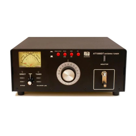
- Page 4 Front Panel Description trol provides coarse adjustment. 10. When you have tuned your antenna to the best SWR, record Operating Your AT1500DT 12 the settings of the INPUT, ANTENNA and INDUCTANCE controls on the chart above for future reference. When you Before Operating retune, use these settings as your starting point.
- Page 5 WARNING: DO NOT OPERATE THE AT1500DT WITH THE COVER OFF. Before Operating 1. To avoid possible damage to the AT1500DT set TUNE, IN- DUCTOR, and POWER RANGE switches as outlined in the chart before applying transmitter power. 2. Begin tuning with your transmitter/amp into the tuner set at a low output power setting (50-100 Watts).
- Page 6 BALANCED OUT selects the balanced and End Fed Wire output connectors located after the crank handle. Coupled to the crank handle impedance matching circuit. is a gear-driven precision mechanical counter. 1-800-773-7931 WWW.PALSTAR.COM 1-800-773-7931 WWW.PALSTAR.COM...
- Page 7 Location plied jumper strap between the Select a location for the lower BALANCED OUTPUT and AT1500DT that allows the con- the END FED WIRE posts (see nectors to be free form any pos- pg 10). sible contact during operation to...
- Page 8 AT11500DT Schematic AT1500DT Schematic MODEL AT1500DT DIFF-T TUNER 385-0-385 pf DIFF-T variable capacitor PEAK PEAK/HOLD (Front Panel) 1-800-773-7931 WWW.PALSTAR.COM 1-800-773-7931 WWW.PALSTAR.COM...
Need help?
Do you have a question about the AT1500DT and is the answer not in the manual?
Questions and answers