Table of Contents
Advertisement
Advertisement
Table of Contents

Related Manuals for Palstar AT1KM


Summary of Contents for Palstar AT1KM
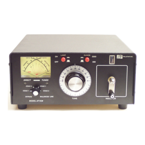
- Page 1 Palstar Incorporated AT1KM 1200 Watt Antenna Tuner 9676 N. Looney Rd., Piqua, OH 45356 USA Owner’s Manual Customer Service and Sales Telephone: 1-800-773-7931 Fax: 1-937-773-8003 Email: info@palstar.com © Copyright 2005 Palstar Inc. Printed in the U.S.A.
-
Page 2: Important Safeguards
(servicing) instructions in the literature accompanying the appliance. at its option at the Palstar factory in Our service rate is $30 per hour (1/2 WARNING: TO REDUCE THE RISK OF FIRE OR ELECTRIC SHOCK, DO NOT Piqua, OH. - Page 3 Operating Your AT1KM cont’d Important Safeguards cont’d Notes: 14. Power Lines—An outside antenna sys- technician to restore the product to its normal tem should not be located in the vicinity of operation. overhead power lines, other electric light or e. If the product has been dropped or the power circuits, where it can fall into such cabinet has been damaged.
-
Page 4: Table Of Contents
Table of Contents Operating Your AT1KM cont’d 8. Key your transmitter and adjust the 10. When you have tuned your an- Thank you for purchasing a Please carefully read the power level for a reading of 100-150 tenna to the best SWR, record the Palstar AT1KM Antenna Tuner. -
Page 5: General Description
4. If you use a linear amplifier, set it to Standby. Do not use the linear ampli- 1. To avoid possible damage to the fier until the AT1KM is tuned. Do not AT1KM set INPUT, OUTPUT, IN- exceed 800 watts average (single DUCTOR, and POWER RANGE tone). -
Page 6: Specifications
BALANCED OUT selects the balanced and End crank handle. Coupled to the crank handle Fed Wire output connectors located after the is a gear-driven precision mechanical impedance matching circuit. counter. 5. TUNE Continuously adjustable differen- tial capacitor. 1-800-773-7931 WWW.PALSTAR.COM 1-800-773-7931 WWW.PALSTAR.COM... -
Page 7: Installation
WIRE post. OUTPUT posts, and the sup- Location plied jumper strap between the Select a location for the AT1KM lower BALANCED OUTPUT and that allows the connectors to be the END FED WIRE posts (see free form any possible contact pg 10). -
Page 8: At1Km Schematic
AT1KM Schematic AT1KM Schematic 1-800-773-7931 WWW.PALSTAR.COM 1-800-773-7931 WWW.PALSTAR.COM...
Need help?
Do you have a question about the AT1KM and is the answer not in the manual?
Questions and answers