Palstar AT5K Owner's Manual
3500 watt antenna tuner
Hide thumbs
Also See for AT5K:
- Owner's manual (10 pages) ,
- Owner's manual (15 pages) ,
- Technical manual (9 pages)

Subscribe to Our Youtube Channel
Related Manuals for Palstar AT5K


Summary of Contents for Palstar AT5K
- Page 1 AT5K 3500 Watt Antenna Tuner Owner’s Manual © Copyright 2005– 2009 Palstar Inc. Printed in the U.S.A.
-
Page 2: Important Safeguards
This product should not be placed in a built-in left unattended and unused for long periods of installation such as a bookcase or rack unless time, unplug it from the wall outlet. 1-800-773-7931 WWW.PALSTAR.COM... - Page 3 An improper adjust- mation. ment may result in damage and will often e. Use jumper wire not smaller than No.6 require extensive work by a qualified AWG copper or equivalent, when a separate antenna grounding electrode is used. 1-800-773-7931 WWW.PALSTAR.COM...
-
Page 4: Table Of Contents
Table of Contents Thank you for purchasing a Please carefully read the Palstar AT5K Antenna Tuner. Owner’s Manual in order to take This antenna tuner has been advantage of the many interest- designed and manufactured to ing features that will provide... -
Page 5: General Description
Integrated into the AT5K is a rating of 3500 watts (single tone frequency-compensated lighted- continuous) and 5000 watts dial dual-movement SWR me- PEP at certain Z ranges (p.14). -
Page 6: Installation
Location Select a location for the AT5K that allows the connectors to be free from any possible contact with people, pets, or objects during operation and with unrestricted air flow for cooling. - Page 7 @ 500mA to power output to dummy load or reso- the metering, lamp, nant antenna. Bypasses tuner, relay and fan. but meter circuits are on if 12VDC adaptor is connected to jack located on rear panel. FIGURE 1 REAR PANEL CONNECTORS 1-800-773-7931 WWW.PALSTAR.COM...
-
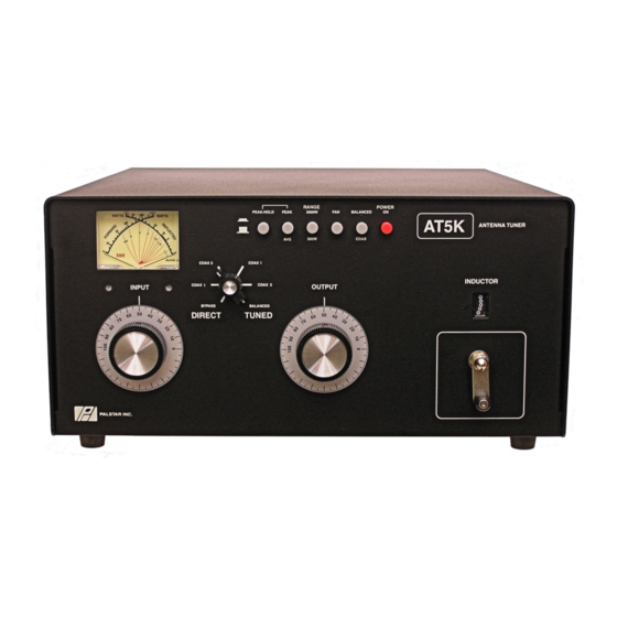
Page 8: Front Panel Description
Front Panel Description 4 5 6 1. POWER/SWR METER Dual needle meter displays FORWARD and REFLECTED power in watts. SWR is measured where the two needles intersect on the red scale. 2. PEAK AND PEAK/HOLD Active circuitry is used to offer peak reading for SSB. - Page 9 Front Panel Description 6. POWER ON The IN position provides power for the Peak and Peak Hold metering circuit, relay and meter illumination. 7. INDUCTOR 28 H continuously variable ceramic roller inductor driven by a crank handle. Coupled to the crank handle is a gear-driven precision me- chanical counter.
-
Page 10: Schematic
AT5K Schematic... - Page 11 AT5K Schematic...
-
Page 12: Operating Your At5K
Operating Your AT5K Before Operating 1. To avoid possible damage to the AT5K set INPUT, OUTPUT, INDUCTOR, and POWER RANGE switches as outlined in the chart before applying trans- mitter power. 2. Begin tuning with your transmitter/lamp into the tuner set at a low output power setting (50-150 Watts). - Page 13 3. Very high or very low impedance loads are to be approached with extra cau- tion especially when you are going to use high power and the use of an RF analyzer (e.g. the Palstar ZM30 Antenna Analyzer) would be advisable to check and understand the kind of load you attempting to use.
- Page 14 Troubleshooting You hear a spitting sound while tuning your AT5K at high power. You are probably tuning into an impedance that is on the low side (20Ω – 40Ω). In this event, either reduce transmitter/amplifier power to a lower setting or change to a higher antenna impedance by using a different antenna or modifying the existing antenna.
-
Page 15: Specifications
16” Wide x 8” High x 18” Deep (incl. terminals) Weight 25 lbs. Materials Chassis, brackets, and top cover are gold chem-film coated aluminum (.090) & powder coated. Front Panel Front panel is matte powder coated and screened. 1-800-773-7931 WWW.PALSTAR.COM... -
Page 16: Service And Warranty
14 days of purchase. Returned repair or replacement of the product; items are subject to a 25% restocking at its option at the Palstar factory in fee. Shipping is not refundable. Piqua, OH. NOTE:... - Page 17 Notes 1-800-773-7931 WWW.PALSTAR.COM...
- Page 18 18 Notes 1-800-773-7931 WWW.PALSTAR.COM...
- Page 19 Notes 19 1-800-773-7931 WWW.PALSTAR.COM...
- Page 20 Palstar Incorporated 9676 N. Looney Rd., Piqua, OH 45356 USA Customer Service and Sales Telephone: 1-800-773-7931 Fax: 1-937-773-8003 Email: info@palstar.com REV 1.4 01.09.2009...
Need help?
Do you have a question about the AT5K and is the answer not in the manual?
Questions and answers