Table of Contents
Advertisement
Quick Links
Advertisement
Table of Contents

Related Manuals for Palstar AT4K


Summary of Contents for Palstar AT4K
- Page 1 Palstar Incorporated AT4K 2500 Watt Antenna Tuner 9676 N. Looney Rd., Piqua, OH 45356 USA Owner’s Manual Customer Service and Sales Telephone: 1-800-773-7931 Fax: 1-937-773-8003 Email: info@palstar.com © Copyright 2008 Palstar Inc. Printed in the U.S.A. VER 1.5 2008_04...
-
Page 2: Important Safeguards
(servicing) instructions in the repair or replacement of the prod- literature accompanying the appliance. uct; at its option at the Palstar NOTE: WARNING: TO REDUCE THE RISK OF FIRE OR ELECTRIC SHOCK, DO NOT EXPOSE THIS APPLIANCE TO RAIN OR MOISTURE. DO NOT factory in Piqua, OH. - Page 3 Note: These adjustments control the calibration and accuracy of the 14. Power Lines—An outside antenna sys- technician to restore the product to its normal AT4K metering. Do not adjust unless you are sure the metering is tem should not be located in the vicinity of operation.
-
Page 4: Table Of Contents
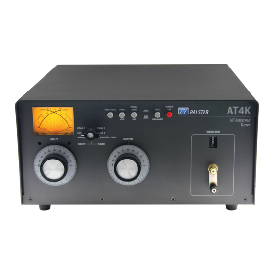
Specifications Table of Contents Front Panel Indicators and Controls Thank you for purchasing a Palstar AT4K Antenna Tuner. This antenna tuner has been designed and manufactured to high qual- Metering Dual movement cross needle power and frequency ity standards, and will provide reliable operation for many years. -
Page 5: General Description
Ω load @3.5Mhz can provide unbalanced or bal- If you hear a spitting sound while anced output. Integrated into the AT4K is a Ant Cap Inductor Voltage Loss tuning your AT4K at high power, frequency compensated, lighted you are probably tuning into an imp- 100 pF 11.7 H... -
Page 6: Installation
Be sure to write down the new settings for future Location For a balanced feed antenna, use with that antenna Select a location for the AT4K connect a balanced feedline to that allows the connectors to be the white BALANCED OUTPUT 5. - Page 7 BE APPROACHED WITH EXTRA CAUTION, ESPECIALLY WHEN YOU ARE GOING TO USE HIGH POWER. THE USE OF AN RF ANALYZER (E.G. A PALSTAR ZM-30 AN- TENNA ANALYZER) WOULD BE ADVISABLE TO MEAS- URE AND UNDERSTAND THE KIND OF LOAD YOU ARE ATTEMPTING TO USE.
-
Page 8: Front Panel Description
Front Panel Description Operating Your AT4K 4. Set POWER RANGE switch to 300 W (Power Range Me- 3 4 5 6 ter Switch button OUT). 5. Set OUPUT SELECTOR switch to the position matching your antenna connection. To tune your antenna, the switch selection must be set to: COAX 1 TUNED, COAX 2 TUNED or WIRE (BALANCED ANTENNA). -
Page 9: Before Operating
TUNED COAX 1 Selects COAX 1 connector through the CAUTION — Before Operating impedance matching T circuit. 1. To avoid possible damage to the AT4K set INPUT, OUT- e. TUNED COAX 2 Selects COAX 2 connector through the PUT, and INDUCTOR controls as outlined in the chart be- tuner matching T circuit. -
Page 10: At4K Schematic
AT4K Schematic AT4K Schematic 1-800-773-7931 WWW.PALSTAR.COM...
Need help?
Do you have a question about the AT4K and is the answer not in the manual?
Questions and answers