Advertisement
Palstar Incorporated
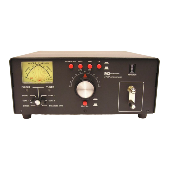
AT1KP 1200 Watt Antenna Tuner
9676 N. Looney Rd.,
Piqua, OH 45356 USA
Customer Service and Sales Telephone:
160 Meter to 6 Meter
1-800-773-7931
Peak/Peak Hold Metering
Fax:
Differential-T Antenna Tuner
1-937-773-8003
Email:
info@palstar.com
Owner's Manual
© Copyright 2007 Palstar Inc.
Printed in the U.S.A.
REV 1.2 01.22.2008
Advertisement
Table of Contents

Related Manuals for Palstar AT


Summary of Contents for Palstar AT
- Page 1 9676 N. Looney Rd., Piqua, OH 45356 USA Customer Service and Sales Telephone: 160 Meter to 6 Meter 1-800-773-7931 Peak/Peak Hold Metering Fax: Differential-T Antenna Tuner 1-937-773-8003 Email: info@palstar.com Owner’s Manual © Copyright 2007 Palstar Inc. Printed in the U.S.A. REV 1.2 01.22.2008...
-
Page 2: Important Safeguards
Return Policy EXPOSE THIS APPLIANCE TO RAIN OR MOISTURE. DO NOT ment of the product; at its option at All returns must receive prior authori- OPEN THE CABINET WHILE OPERATING. REFER SERVICING TO the Palstar factory in Piqua, OH. - Page 3 AWG copper or equivalent, when a separate antenna grounding electrode is used. Peak Peak High Peak Peak Power On/Off Hold Range Note: The adjustment pots on your meter board may differ in appearance from the photograph. 1-800-773-7931 WWW.PALSTAR.COM 1-800-773-7931 WWW.PALSTAR.COM...
-
Page 4: Table Of Contents
General Description 9. Read the SWR on the red scale at rod that guides the roller wheel as this the point where the two needles inter- will contaminate the windings on the Specifications sect. -
Page 5: General Description
AT1KP is tuned. Do not 2. Begin tuning with your transmitter/ exceed 800 watts average (single amp into the tuner set at a low output tone) during tune-up. power setting (50-100 Watts). 5. Set RANGE switch to 300 W WARNING: DO NOT OPERATE THE AT1KP WITH THE COVER OFF. -
Page 6: Specifications
BALANCED OUT selects the balanced and crank handle. Coupled to the crank handle End Fed Wire output connectors located after the is a gear-driven precision mechanical impedance matching circuit. counter. 7. TUNE Continuously adjustable 1-800-773-7931 WWW.PALSTAR.COM 1-800-773-7931 WWW.PALSTAR.COM... -
Page 7: Installation
END FED stricted air flow for cooling. WIRE post and remove the WARNING: Balanced antennas will produce high RF voltages at the output post connectors. RF burns may result if touched during transmission. jumper strap. When using an Installation Procedures END FED WIRE antenna the GROUND connector. -
Page 8: At1Kp Schematic
AT1KP Schematic AT1KP Schematic 1-800-773-7931 WWW.PALSTAR.COM 1-800-773-7931 WWW.PALSTAR.COM...
Need help?
Do you have a question about the AT and is the answer not in the manual?
Questions and answers