Table of Contents
Advertisement
Advertisement
Table of Contents

Related Manuals for Palstar AT1500CV


Summary of Contents for Palstar AT1500CV
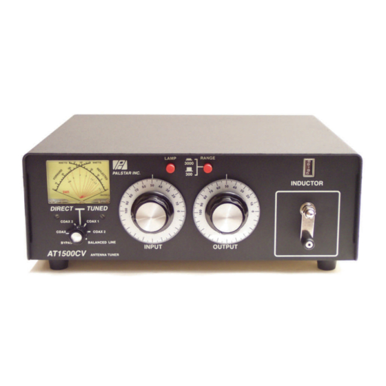
- Page 1 Palstar Incorporated AT1500CV 1500 Watt Antenna Tuner 9676 N. Looney Rd., Piqua, OH 45356 USA Owner’s Manual Customer Service and Sales Telephone: 1-800-773-7931 Fax: 1-937-773-8003 Email: info@palstar.com © Copyright 2005 Palstar Inc. Printed in the U.S.A.
-
Page 2: Important Safeguards
The exclamation point within an equilateral (the “Warranty Period”). Palstar Inc’s triangle is intended to alert the user to the erly. Palstar, Inc. is not responsible for presence of important operating and obligation under this warranty is lim- merchandise damaged in shipment. - Page 3 Operating Your AT1500CV cont’d Important Safeguards cont’d Notes 14. Power Lines—An outside antenna sys- technician to restore the product to its normal tem should not be located in the vicinity of operation. overhead power lines, other electric light or e. If the product has been dropped or the 1.
-
Page 4: Table Of Contents
Operating Your AT1500CV cont’d Table of Contents Thank you for purchasing a Please carefully read the Palstar AT1500CV Antenna Owner’s Manual in order to take 7. Rotate the INPUT, ANTENNA and Tuner. This antenna tuner has advantage of the many interest-... -
Page 5: General Description
4. If you use a linear amplifier, set it to AT1500CV set INPUT, OUTPUT, Standby. Do not use the linear ampli- INDUCTOR, and POWER RANGE fier until the AT1500CV is tuned. Do switches as outlined in the chart below not exceed 1200 watts average before applying transmitter power. -
Page 6: Specifications
Coupled to the crank handle line post using a copper jumper strap. is a gear-driven precision mechanical counter. 5. OUTPUT Continuously adjustable output capacitor. 6. INPUT Continuously adjustable input capacitor. 1-800-773-7931 WWW.PALSTAR.COM 1-800-773-7931 WWW.PALSTAR.COM... -
Page 7: Installation
Location ANCED OUTPUT post (back Select a location for the panel) and connect a jumper to AT1500CV that allows the con- the lower white Nylon66 BAL- nectors to be free from any pos- ANCED OUTPUT post. sible contact during operation... -
Page 8: At1500Cv Schematic
AT1500CV Schematic AT1500CV Schematic 315pf 315pf 26uH 1-800-773-7931 WWW.PALSTAR.COM 1-800-773-7931 WWW.PALSTAR.COM...
Need help?
Do you have a question about the AT1500CV and is the answer not in the manual?
Questions and answers