Table of Contents
Advertisement
Quick Links
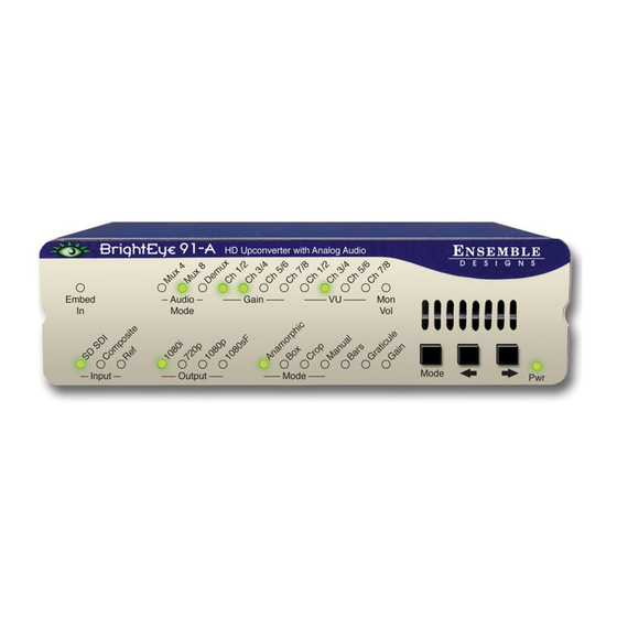
BrightEye 91-A
HD Upconverter
with Analog Audio
This user guide provides detailed information for using the BrightEye 91-A HD
upconverter with analog audio output.
The information is organized into the following sections:
• Product Overview
• Functional Description
• Applications
• Rear Connectors
• Operation
• Front Panel Controls and Indicators
• Using The BrightEye Control Application
• Warranty and Factory Service
• Specifications
• Glossary
User Guide
BrightEye-1
TM
Revision 2.2 SW v1.2.0
Advertisement
Table of Contents

Related Manuals for Ensemble Designs BrightEye 91-A


Summary of Contents for Ensemble Designs BrightEye 91-A
-
Page 1: User Guide
HD Upconverter with Analog Audio User Guide Revision 2.2 SW v1.2.0 This user guide provides detailed information for using the BrightEye 91-A HD upconverter with analog audio output. The information is organized into the following sections: • Product Overview • Functional Description •... -
Page 2: Product Overview
As shown in the diagram below, when a standard definition serial digital video input is fed to the BrightEye 91-A, the signal enters the serial digital receiver and is frame synchronized to the reference input. Audio is disembedded and passed around the upconversion process. - Page 3 Ch 5/6 Outputs Ch 7/8 Audio I/O selectable as: Mux 8 = 8 inputs or Mux 4 = 4 in/4 out or Demux = 8 outputs Provides embedded pass through of all 16 audio channels BrightEye 91-A Functional Block Diagram BrightEye-3...
- Page 4 BrightEye 91-A HD Upconverter with Analog Audio PERFORMANCE ADVANTAGES OF THE BRIGHTEYE SERIES When images are converted between different formats, color spaces, and resolu- tion geometries, the need for accuracy and fidelity are extremely important. Whether upconverting from standard definition to HD formats, converting between different HD formats, or downconverting to SD, extra care must be paid to every aspect of the signal and the content of the images.
- Page 5 The BrightEye 91-A can upconvert SD video from many different source types. As shown in the example below, the SD ingest signal from a satellite is fed to a BrightEye 91-A where it is upconverted to feed an HD Master Control Switcher. The other output can be sent to another HD destination.
-
Page 6: Rear Connectors
BrightEye 91-A HD Upconverter with Analog Audio REAR CONNECTORS All connections to the BrightEye 91-A are made on the rear of the unit. Refer to the photo below. BrightEye 91-A Rear Connectors Power Connection Connect a modular power supply to the 12 volt DC power input connection on the far left of the unit. -
Page 7: Operation
Mux 4, two Phoenix connectors are inputs and two Phoenix connectors are outputs. OPERATION Control and operation of the BrightEye 91-A is performed from the front panel or remotely from a networked PC with the BrightEye PC or BrightEye Mac Control application. - Page 8 BrightEye 91-A HD Upconverter with Analog Audio Audio Mode Indicates the currently selected audio I/O mode. Choices are Mux 4 (4 inputs and 4 outputs), Mux 8 (8 inputs), or Demux (8 outputs). Gain (Audio) These controls allow for quick adjustment of Gain level for the channel pairs.Gain adjustment is done in conjunction with the VU indicators.
-
Page 9: Adjusting Parameters From The Front Panel
USING THE BRIGHTEYE CONTROL APPLICATION The BrightEye PC and BrightEye Mac applications included on CD-ROM are designed to allow you to configure and control the BrightEye 91-A from a personal computer. Installation and instructions for using this software applica- tion are given in the PDF manual on disk. - Page 10 BrightEye 91-A HD Upconverter with Analog Audio Mode • Mode – use this control to set the aspect ratio for the upconverted HD video output (Anamorphic, Pillar Box, Crop, Manual). When Manual is selected, use the Manual menu to set the aspect ratio.
- Page 11 BrightEye 91-A Config • Noise Reduce – adjusts the amount of noise reduction on the output signal from Low, Medium, or High. The typical setting for this parameter is Off or Low. • Detail – adjusts the amount of picture detail enhancement on the output from Low, Medium, or High.
- Page 12 HDMI Non-Compat, HDMI Native, HDMI Compatible). Status information comes from the display itself. Some displays may not work with the BrightEye 91-A, depending on the formats that the display supports. For best results, use a display that is HDMI Native.
- Page 13 BrightEye 91-A • Hor Flip – Horizontal Flip is a special Mirror Output Mode that is useful for flipping the image left-to-right for use with on-screen talent or with prism lens cameras. Select On to flip the output image left to right. Select Off (after Reset) to turn Mirror Output Mode off.
- Page 14 BrightEye 91-A HD Upconverter with Analog Audio Aud Input The appearance of the Input menu will depend on the mode selected and the type of audio used. Multiplexer Mode When the module is set for Mux 8, the Input menu provides the controls shown below: •...
- Page 15 BrightEye 91-A • Group A Select – select the audio group to multiplex from Group 1, Group 2, Group 3, Group 4, or Off for either control. Demultiplexer Mode When the module is set for Demux, the Input menu provides the controls shown below.
- Page 16 BrightEye 91-A HD Upconverter with Analog Audio Mixer B For Channels 5 – 8, use the Mixer B menu shown below to set the following: • Input Ch 5 – assign Input Channel 5 to the desired output bus or tie to Channel 6.
- Page 17 BrightEye 91-A Audio Out • Mon Assign – chooses the audio pair that is output on the Audio Monitor headphone jack. Choices are: Chan 1/2, Chan 3/4, Chan 5/6, Chan 7/8, Chan 9/10, Chan 11/12, Chan 13/14, Chan 15/16. • Mon Volume – sets the volume level sent to the headphone jack (range is from 0 to 100%, default is 100%).
-
Page 18: Warranty And Factory Service
WARRANTY AND FACTORY SERVICE Warranty Ensemble Designs, Inc. warrants this product to be free from defect in material and workmanship for a period of 5 years from the date of delivery. During this 5 year warranty period, Ensemble Designs, Inc. will repair any defective units at Ensemble’s expense if the unit should be determined to be defective after con-... -
Page 19: Specifications
BrightEye 91-A SPECIFICATIONS Analog Video Input: Number: Signal Type: Analog Composite PAL or NTSC Impedance: 75 Ω Return Loss: > 40 dB Input DC: +/- 1 volt DC Input Hum: < 100 mV Serial Digital Input: Number: Signal Type: 270Mb/s SD Serial Digital (SMPTE 296M) Impedance: 75 Ω... - Page 20 BrightEye 91-A HD Upconverter with Analog Audio Analog Audio Outputs: Number: Eight (selectable as inputs or outputs) Type: Balanced, transformerless Impedance: 30 Ω Max Output Level: 24 dBu Resolution 24 bits, 128x Oversmapled Reference Level: -10 dBu or + 4 dBu Frequency Response: ±...
-
Page 21: Brighteye Power Supply Information
BrightEye 91-A BRIGHTEYE POWER SUPPLY INFORMATION Below is a list of power supplies and optional items that may have come with your BrightEye: BEPS BrightEye Individual Power Supply. BEPS6 Spider Power Supply. This powers 6 single high BrightEyes or 3 double high BrightEyes (BrightEye 90 family). - Page 22 BrightEye 91-A HD Upconverter with Analog Audio GLOSSARY This is a brief glossary of commonly used terms associated with this product. AES/EBU The digital audio standard defined as a joint effort of the Audio Engineering Society and the European Broadcast Union. AES/EBU or AES3 describes a serial bitstream that carries two audio channels, thus an AES stream is a stereo pair.
- Page 23 BrightEye 91-A Chroma The color or chroma content of a signal, consisting of the hue and saturation of the image. See also Color Difference. Component In a component video system, the totality of the image is carried by three separate but related components. This method provides the best image fidelity with the fewest artifacts, but it requires three independent transmission paths (cables).
- Page 24 BrightEye 91-A HD Upconverter with Analog Audio dBFS In Digital Audio systems, the largest numerical value that can be represented is referred to as Full Scale. No values or audio levels greater than FS can be repro- duced because they would be clipped. The nominal operating point (roughly corre- sponding to 0 VU) must be set below FS in order to have headroom for audio peaks.
- Page 25 BrightEye 91-A The International Electrotechnical Commission provides a wide range of worldwide standards. They have provided standardization of the AC power con- nection to products by means of an IEC line cord. The connection point uses three flat contact blades in a triangular arrangement, set in a rectangular connector.
- Page 26 BrightEye 91-A HD Upconverter with Analog Audio Multimode Multimode fibers have a larger diameter core (either 50 or 62.5 microns), and a correspondingly larger aperture. It is much easier to couple light energy into a multimode fiber, but internal reflections will cause multiple “modes” of the signal to propagate down the fiber.
- Page 27 BrightEye 91-A Return Loss An idealized input or output circuit will exactly match its desired impedance (generally 75 ohms) as a purely resistive element, with no reactive (capacitive or inductive elements). In the real world we can only approach the ideal. So our real inputs and outputs will have some capacitance and inductance.
- Page 28 BrightEye 91-A HD Upconverter with Analog Audio A Time Base Corrector is a system to reduce the Time Base Error in a signal to acceptable levels. It accomplishes this by using a FIFO (First In, First Out) memory. The incoming video is written into the memory using its own jittery timing.
Need help?
Do you have a question about the BrightEye 91-A and is the answer not in the manual?
Questions and answers