Table of Contents
Advertisement
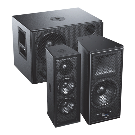
ULTRA XP
OPERATING INSTRUCTIONS
UPJ-1XP Compact VariO Loudspeaker
UPJunior-XP UltraCompact VariO Loudspeaker
UPM-1XP UltraCompact Wide-Coverage Loudspeaker
UPM-2XP UltraCompact Narrow-Coverage Loudspeaker
UMS-1XP UltraCompact Subwoofer
Keep these important operating instructions.
Check www.meyersound.com for updates.
Advertisement
Table of Contents

Related Manuals for Meyer Sound ULTRA XP


Summary of Contents for Meyer Sound ULTRA XP
-
Page 1: Operating Instructions
ULTRA XP OPERATING INSTRUCTIONS UPJ-1XP Compact VariO Loudspeaker UPJunior-XP UltraCompact VariO Loudspeaker UPM-1XP UltraCompact Wide-Coverage Loudspeaker UPM-2XP UltraCompact Narrow-Coverage Loudspeaker UMS-1XP UltraCompact Subwoofer Keep these important operating instructions. Check www.meyersound.com for updates. - Page 2 The contents of this manual are furnished for informational purposes only, are subject to change without notice, and should not be con- strued as a commitment by Meyer Sound Laboratories Inc. Meyer Sound assumes no responsibility or liability for any errors or inaccura- cies that may appear in this manual.
-
Page 3: Table Of Contents
Latency of Ultra XP Loudspeakers Chapter 2: Ultra XP Loudspeakers Loudspeaker Input Connector Current Draw and Cable Requirements for Ultra XP Loudspeakers Belden 1502 Cable (or Equivalent) Long Cable Runs with Separate Cable for DC Power and Audio EN3-to-Pigtail Cables... - Page 4 CONTENTS...
-
Page 5: Chapter 1: Introduction
1502 or equivalent) allows a single cable to carry both DC TIP: A tip offers a helpful tip relevant to the topic power and balanced audio to Ultra XP loudspeakers. Ultra XP at hand. amplifier and signal-processing circuits store DC power and... - Page 6 CHAPTER 1: INTRODUCTION UPJunior-XP UltraCompact VariO UPM-2XP UltraCompact Narrow-Coverage Loudspeaker Loudspeaker UPJunior-XP Loudspeaker UPM-2XP Loudspeaker The UPJunior-XP ultracompact VariO loudspeaker includes The UPM-2XP ultracompact narrow-coverage loudspeaker one 8-inch cone driver with neodymium magnet, and one 2- includes two 5-inch cone drivers, and one 1-inch metal inch compression driver coupled to a rotatable, constant- dome tweeter on a constant-directivity, 45-degree symmet- directivity 80-degree by 50-degree horn.
-
Page 7: Mps-488Hp Intelligentdc High-Power Eight-Channel Power Supply
MPS-488HP Operating Instructions (PN 05.205.005.01). LATENCY OF ULTRA XP LOUDSPEAKERS There is a very small latency of 1.58 ms for Ultra XP loud- speakers when compared to their equivalent AC-based models. This does not represent a problem when using Ultra XP loudspeakers with other Ultra XP loudspeakers. - Page 8 CHAPTER 1: INTRODUCTION...
-
Page 9: Chapter 2: Ultra Xp Loudspeakers
CHAPTER 2: ULTRA XP LOUDSPEAKERS LOUDSPEAKER INPUT CONNECTOR Ultra XP loudspeakers receive DC power and balanced audio from a single input connector, available as Phoenix™ 5-pin male, SwitchCraft ® EN3™ 5-pin male, or ECO-M 7-pin male. The sealed EN3 and ECO-M connectors are ideal for outdoor, all-weather use. -
Page 10: Current Draw And Cable Requirements For Ultra Xp Loudspeakers
Cable Lengths and Cable Gauges cables is with a multiconductor cable such as Belden 1502, Cable lengths up to 150 feet between the Ultra XP loud- which has dedicated conductors for DC power and bal- speakers and their external power supply are supported anced audio in a single jacket. -
Page 11: Long Cable Runs With Separate Cable For Dc Power And Audio
For more information on cable assem- LIMIT LEDS bly, refer to Appendix B, “Assembling Loud- When source levels for an Ultra XP loudspeaker exceed speaker Cables.” maximum input levels for its drivers, limiting is engaged and is indicated by the two Limit LEDs on the rear user panel. -
Page 12: On/Status Led
On/Status LED changes from yellow to green and the limiter threshold returns to normal. Amplifier Cooling System Amplifiers for Ultra XP loudspeakers rely solely on natural convection for cooling from air flowing over their heat sinks. The efficient amplifier and heat sink design keeps tempera-... -
Page 13: Chapter 3: Powering Ultra Xp Loudspeakers
DC power and balanced audio to up to eight Phoenix 5-pin male to Phoenix 5-pin female cables. Ultra XP loudspeakers, or other Meyer Sound IntelligentDC loudspeakers. Composite multiconductor cables, such as Belden 1502 or equivalent, can deliver both DC power and... - Page 14 CHAPTER 3: POWERING ULTRA XP LOUDSPEAKERS gauge for the DC cable so you can achieve longer ■ To join two EN3 cables, one with an EN3 5-pin male cable runs (see “Long Cable Runs with Separate cable mount connector to one with an EN3 5-pin female Cable for DC Power and Audio”...
-
Page 15: Chapter 4: Mounting Ultra Xp Loudspeakers
CHAPTER 4: MOUNTING ULTRA XP LOUDSPEAKERS IMPORTANT SAFETY CONSIDERATIONS ULTRA XP LOUDSPEAKER RIGGING OPTIONS When installing Meyer Sound loudspeakers, the following Ultra XP loudspeakers include the following rigging options. precautions should always be observed: Loudspeaker Rigging All Meyer Sound products must be used in accordance ■... -
Page 16: U-Brackets
U-BRACKETS The following U-brackets are available for Ultra XP loudspeakers. All Ultra XP U-brackets can be mounted on walls and ceil- ings (under balcony and canopy areas), while some can also be mounted on floors (for stage monitoring and frontfill applica- tions), trusses, and poles. - Page 17 ULTRA XP OPERATING INSTRUCTIONS MUB-UPJ U-Bracket, Wall Mount, Vertical and Horizontal (Left), Ceiling Mount and Floor Mount (Right) MUB-UPJunior U-Bracket with Array Adapters, Truss-Mounted (Left), Pole-Mounted (Right)
- Page 18 CHAPTER 4: MOUNTING ULTRA XP LOUDSPEAKERS MUB-UPM U-Bracket, Wall Mount, Vertical and Horizontal (Left), Ceiling Mount and Floor Mount (Right) UMS-SM U-Bracket, Exploded View (Left), Installed (Right)
-
Page 19: Mounting Yokes
ULTRA XP OPERATING INSTRUCTIONS MOUNTING YOKES The following mounting yokes are available for the UPJ-1XP, UPJunior-XP, UPM-1XP, and UPM-2XP loudspeakers. The yokes suspend a single loudspeaker and allow a wide range of horizontal and vertical adjustment. The yokes for the UPJ-1XP and UPJunior-XP attach to the bottom end plate. -
Page 20: Poles And Pole-Mount Adapters
UPJ-1XP or UPJunior-XP loudspeaker; it can also mount two cabinets with a U-bracket and array adapter kit (see Figure 2 on page 19). The MPS-UMS pole allows a single Ultra XP loudspeaker to be mounted above the UMS-1XP subwoofer (Figure 3 on page 21). -
Page 21: Eyebolt Rigging For Upj-1Xp And Upjunior-Xp
However, two eyebolts provide more safety and stability, as well the capability of aiming and tilting the loudspeaker for targeted coverage. Ultra XP with One Eyebolt (Left) and Two Eyebolts (Right) NOTE: Up to two UPJ-1XPs UPJunior-XPs, oriented vertically, can be suspended with the eyebolts supplied by Meyer Sound at a 7:1 safety factor. -
Page 22: Array Adapters For Upj-1Xp And Upjunior-Xp
CHAPTER 4: MOUNTING ULTRA XP LOUDSPEAKERS ARRAY ADAPTERS FOR UPJ-1XP AND UPJUNIOR-XP M8 screw to Eyebolt M8 screw to loudspeaker loudspeaker Array adapter plates are available for the UPJ-1XP (MAAM-UPJ) and UPJunior-XP (MAAM-UPJunior) to form horizontal and vertical arrays of up to three loudspeakers. - Page 23 ULTRA XP OPERATING INSTRUCTIONS Array adapters can also be used to position UPJ-1XPs and Vertical Arrays UPJunior-XPs as floor monitors with adjustable angles. Vertical arrays with the array adapter can be flown by When positioning the loudspeakers as floor monitors, the...
- Page 24 CHAPTER 4: MOUNTING ULTRA XP LOUDSPEAKERS the array adapter plate’s rear pickup holes for addi- tional support or to provide control over the vertical tilt. TIP: To create optimum coverage in vertical arrays, the splay angles between loudspeakers should be 30 degrees when the VariO horns are in the 40°...
-
Page 25: Appendix A: Ultra Xp Accessories
EN3 5-pin female cable mount connector LOUDSPEAKER CABLES The following loudspeaker cables are available from Meyer Sound and can be used to connect Ultra XP loudspeakers to MPS-488HP power supplies. NOTE: Phoenix and EN3 loudspeaker cables and bulk cable use Belden 1502R (regular) or Belden 1502P (plenum) cable. - Page 26 The following rain hoods are available from Meyer Sound. Ultra XP Rain Hoods Part Number Rain Hood To be used with vertically oriented Ultra XP loudspeakers: 40.196.062.02 Vertical Rain Hood UPJ-1XP, UPJunior-XP, UPM-1XP, UPM-2XP, UMS-1XP To be used with horizontally oriented Ultra XP loudspeakers: ...
-
Page 27: Appendix B: Assembling Loudspeaker Cables
Make sure the 48 V DC from the external power supply is wired directly (and only) to the 48 V DC pins on the Ultra XP loudspeaker connector, and that the polarity is observed (negative to negative, positive to positive) to avoid damage to the loudspeaker. - Page 28 APPENDIX B: ASSEMBLING LOUDSPEAKER CABLES 3. Secure the conductors by tightening the five screws in the Phoenix cable mount connector. Screws should be torqued to 5–6 Nm(4.4–5.3 In-Lbs). Tighten screws CAUTION: Screws should not be inserted into the Phoenix connector while the connector rests in a mating plug.
- Page 29 ULTRA XP OPERATING INSTRUCTIONS 2. Insert the five exposed conductors into the five cable holes in a Phoenix 5-pin female cable mount connector. Use the following wiring scheme. Pin 1 Black 48 V DC (–) Pin 2 48 V DC (+)
- Page 30 APPENDIX B: ASSEMBLING LOUDSPEAKER CABLES 6. Solder the five exposed conductors to the five pins on the EN3 cord connector using the following wiring scheme. Dimple identifies Pin 1 Pin 5, White, Pin 5, White, Pin 1, Black, audio (+) audio (+) 48 V DC (–) Pin 2, Red,...
- Page 31 ULTRA XP OPERATING INSTRUCTIONS To assemble an EN3-to-EN3 loudspeaker cable: 1. If the cable has not yet been stripped, strip one end of the cable. Strip the outer shielding by 1 inch and then strip the black, red, blue, and white wires by 0.275 inch.
- Page 32 APPENDIX B: ASSEMBLING LOUDSPEAKER CABLES 5. Repeat the previous steps to attach the EN3 5-pin female connector to the other end of the cable. Dimple identifies Pin 1 Pin 5, White, Pin 5, White, Pin 1, Black, audio (+) audio (+) 48 V DC (–) Pin 2, Red, Pin 4, Blue,...
- Page 33 ULTRA XP OPERATING INSTRUCTIONS 2. Insert the five exposed conductors into the five cable holes in a Phoenix 5-pin female cable mount connector. Use the following wiring scheme. Pin 1 Black 48 V DC (–) Pin 2 48 V DC (+)
- Page 34 APPENDIX B: ASSEMBLING LOUDSPEAKER CABLES 6. Solder the five exposed conductors to the (1, 2, S, 5, and 6) pins on the ECO-M insert connector using the following wir- ing scheme. Pin 5, Blue, Pin 6, White, Pin 5, Blue, audio (–) audio (+) audio (–)
-
Page 35: Appendix C: Vario Horn For Upj-1Xp And Upjunior-Xp
7. Reattach the grille cover and secure it with the four 10- 32 x 5/8” screws. TIP: To rotate the Meyer Sound logo on the grille frame, pull the logo away from the grille frame, rotate it, and release. - Page 36 APPENDIX C: VARIO HORN FOR UPJ-1XP AND UPJUNIOR-XP...
-
Page 37: Appendix D: Optional Rain Hoods And Weather Protection
Item Part Number Quantity VERTICAL RAIN HOOD Horizontal rain hood 66.196.062.01 The Ultra XP vertical rain hood should be used when loud- Pan head screws 101.008 speakers are oriented vertically. Installing the Horizontal Rain Hood Vertical Rain Hood Kit Contents To install the horizontal rain hood: PN 40.196.062.02... - Page 38 APPENDIX D: OPTIONAL RAIN HOODS AND WEATHER PROTECTION WEATHER-PROTECTED UPM-1XP AND UPM-2XP LOUDSPEAKERS Weather-protected versions of the UPM-1XP and UPM-2XP are available for fixed, outdoor installations. The weather- protected cabinets differ from normal models in that the ori- entation of the loudspeaker is flipped and the rear panel connectors are located at the top instead of the bottom.
-
Page 39: Appendix E: Ultra Xp Loudspeaker Specifications
APPENDIX E: ULTRA XP LOUDSPEAKER SPECIFICATIONS Ultra XP Loudspeaker Specifications ACOUSTICAL UPJ-1XP UPJunior-XP UPM-1XP UPM-2XP UMS-1XP Operating Frequency 55 Hz – 20 kHz 70 Hz – 20 kHz 75 Hz – 20 kHz 80 Hz – 20 kHz 25 Hz – 160 Hz Range Note: Recommended maximum operating frequency range. - Page 40 48 V DC 48 V DC 48 V DC 48 V DC 48 V DC Note: Meyer Sound power supply required. For information and specifications on the MPS-488HP IntelligentDC external power supply, refer to its datasheet. PHYSICAL UPJ-1XP UPJunior-XP UPM-1XP...
- Page 41 ULTRA XP OPERATING INSTRUCTIONS Ultra XP Loudspeaker Specifications Humidity To 95% at 45° C (non-condensing) Operating Altitude To 5,000 m (16,404 ft) Non Operating To 12,000 m (39,000 ft) Altitude Shock 30 g 11 msec half-sine on each of 6 sides Vibration 10 Hz –...
- Page 42 APPENDIX E: ULTRA XP LOUDSPEAKER SPECIFICATIONS UPJUNIOR-XP DIMENSIONS 5.88 [149 mm] 9.00 [229 mm] 10.20 [259 mm] 9.25 [235 mm] 19.04 [484 mm] 5.00 [127 mm] UPJunior-XP Dimensions...
- Page 43 ULTRA XP OPERATING INSTRUCTIONS UPM-1XP DIMENSIONS 4.25 [108 mm] 7.70 [196 mm] 18.00 [457 mm] 9.05 9.05 [230 mm] [230 mm] 3.70 6.85 3.90 [94 mm] [174 mm] [99 mm] UPM-1XP Dimensions...
- Page 44 APPENDIX E: ULTRA XP LOUDSPEAKER SPECIFICATIONS UPM-2XP DIMENSIONS 4.25 [108 mm] 7.70 [196 mm] 18.00 [457 mm] 9.05 9.05 [230 mm] [230 mm] 3.70 6.85 3.90 [94 mm] [174 mm] [99 mm] UPM-2XP Dimensions...
- Page 45 ULTRA XP OPERATING INSTRUCTIONS UMS-1XP DIMENSIONS 22.75 17.51 [578 mm] [445 mm] 16.30 [414 mm] UMS-1XP Dimensions...
-
Page 46: Declaration Of Conformity
APPENDIX E: ULTRA XP LOUDSPEAKER SPECIFICATIONS DECLARATION OF CONFORMITY FEDERAL COMMUNICATIONS COMMISSION (FCC) STATEMENT This equipment has been tested and found to comply with the limits for a Class A digital device, pursuant to part 15 of the FCC Rules. These limits are designed to provide reasonable protection against harmful interference when the equipment is operated in a commercial environment. - Page 52 Meyer Sound Laboratories Inc. © 2014 2832 San Pablo Avenue Meyer Sound. All rights reserved. Berkeley, CA 94702 Ultra XP Operating Instructions +1 510 486.1166 PN 05.915.005.01 B www.meyersound.com...
Need help?
Do you have a question about the ULTRA XP and is the answer not in the manual?
Questions and answers