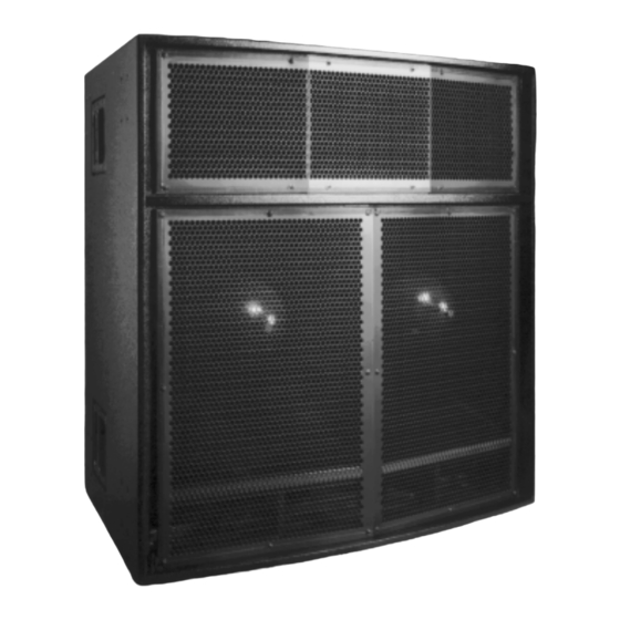
Summary of Contents for Meyer Sound MSL-6
-
Page 1: Operating Instructions
Operating Instructions MSL-6 Self-Powered Loudspeaker System Copyright © 1997 Meyer Sound Laboratories, Inc. All rights reserved Part # 05.053.026.01 Rev A... -
Page 2: Table Of Contents
Low Voltage Directive 73/23/EEC and the EMC Directive 89/336/EEC. Office of Quality Manager Berkeley, California USA October 1, 1995 Made by Meyer Sound, Berkeley, CA, USA European Office: Meyer Sound Germany GmbH Carl Zeiss Strasse 13 56751 Polch, Germany Contents Complete Systems ... -
Page 3: Introduction
275 V and allows any combination of voltage to GND (i.e. Neutral-Hot-GND, Hot-Hot-GND). Continuous voltages higher than 275 V may damage the unit. The MSL-6 uses a NEMA L6-20P or IEC 309 male power inlet and satisfies UL, CSA, and EC safety standards. Voltage Requirements... -
Page 4: Power Connector Wiring Conventions
If the MSL-6 shuts down due to either low or high voltage, the power supply automatically turns on after three seconds if the voltage has returned to either normal operating range. -
Page 5: Safety Issues
For example, since the input imped- ance of a single MSL-6 is 10 k , cascading 20 units produces a balanced input impedance of 500 . If a 150 source is used, the 500 load results in a 2.28 dB loss. -
Page 6: Amplification And Protection Circuitry
Amplification and Protection Circuitry The MSL-6 is powered by the Meyer MP-4, a four- channel 2480 W amplifier (620 W/ch) utilizing comple- mentary power MOSFET output stages (class AB/H). The following sections discuss the MP-4’s limiting circuitry and four-fan cooling system. -
Page 7: Fans And Cooling System
AC power, contact Meyer Sound for repair information. Rigging A single MSL-6 weighs 510 lb (282 kg) and has twelve pivoting lift rings (six on top, six on bottom), each with a maximum working load capacity of 1500 lb (5:1 safety factor). -
Page 8: Measurement And System Integration
LD-1A consisting of two rows of two MSL-6s (lower row at 10 to the top row), one row of two MSL-4s with a 30 horizontal splay angle (hung below lower MSL-6 at 20 ), and 650-Ps on the floor. The diagram on the next page displays connections for half of a complete system;... - Page 9 To insure that the systems combine properly in this area: • Set the MSL-4 to the same polarity as the MSL-6 to phase align the mid-hi frequencies. • Use the CH 5 Array EQ filter to minimize the low- mid rise caused by the MSL-4 array.
-
Page 10: Driver Troubleshooting
MSL-6. The MSL-6 has two rear hatch covers that must be re- moved to access the high and low drivers. Remove the screws for either hatch with a Phillips screwdriver. The hatch is sealed with a rubber gasket so it must be pulled off with moderate force. - Page 11 6 – 12 dB cancellation in the same range. Polarity Between Adjacent Loudspeakers Use the following test procedure to verify the polarity between adjacent MSL-6 loudspeakers: 1. Position two loudspeakers adjacent to each other. 2. Place a measurement microphone six ft from the speakers on the axis between them.
-
Page 12: Dimensions
26.9 14.0 12.5 C.G. 24.2 32.2 (Rigging Typ, both ends) Upper & Lower 3 ⁄16 Braces " Steel, ASTM A36 3 ⁄8 "-16 Reinforcement Rods, B7 Alloy Steel Fluid-Cooled High Frequency Driver, 4-inch Diaphragm (2-inch Throat) " inch ASTM A36 ⁄16 Steel Support Channel Fluid-Cooled Back-... -
Page 13: Risk Of Electric Shock
English • To reduce the risk of electric shock, disconnect the loud- speaker from the AC mains before installing audio cable. Reconnect the power cord only after making all signal connections. • Connect the loudspeaker to a two-pole, three wire grounding mains receptacle. -
Page 14: Gmbh Carl Zeiss Strasse
95-125V 208-235V 50-60Hz 50-60Hz 1400W RMS MAX 1400W RMS MAX Meyer Sound, Berkeley, CA. USA WARNINGS: THIS PRODUCT M This surface may reach high t To ensure proper operation, allow clearance from this surface and a To reduce the risk of electric sho...


Need help?
Do you have a question about the MSL-6 and is the answer not in the manual?
Questions and answers