Advertisement
Table of Contents
- 1 Operating Instructions
- 2 Safety Summary
- 3 Table of Contents
- 4 Introduction
- 5 AC Power
- 6 Audio Input
- 7 Amplification and Protection Circuitry
- 8 Rigging
- 9 Measurement and System Integration Tools
- 10 Complete Systems
- 11 Driver Troubleshooting
- 12 Array Design
- 13 Specifications
- 14 Contact Information
- Download this manual
Advertisement
Table of Contents

Related Manuals for Meyer Sound MSL-4


Summary of Contents for Meyer Sound MSL-4
-
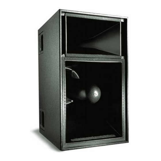
Page 1: Operating Instructions
Operating Instructions MSL-4 Self-Powered Loudspeaker System Front Side Copyright © 1999 Meyer Sound Laboratories, Inc. All rights reserved. Part # 05.031.008.01 Rev C Keep these important operating instructions. -
Page 2: Safety Summary
Safety Summary English Français • To reduce the risk of electric shock, disconnect the loud- • Pour réduire le risque d’électrocution, débranchez la speaker from the AC mains before installing audio cable. prise principale de l’haut-parleur, avant d’installer le Reconnect the power cord only after making all signal câble d’interface allant à... -
Page 3: Table Of Contents
Declaration of Conformity According to ISO/IEC Guide and EN 45014 Declares that the product: The Manufacturer: MSL-4 Meyer Sound Laboratories, Inc. Product Optons: All 2832 San Pablo Avenue Berkeley, California 94702-2204, USA Conforms to the following Product Specifications: Operating temperature:... -
Page 4: Introduction
Windows-based PC. Contact If the MSL-4 shuts down due to either low or high voltage, the Meyer Sound for more information about RMS. power supply automatically turns on after three seconds if the voltage has returned to either normal operating range. - Page 5 Contact Meyer Sound for repair information. Safety Issues Pay close attention to these important electrical and safety issues. Use a power cord adapter to drive the MSL-4 from a standard 3-prong outlet (NEMA 5-15R; 125 V max). earth ground...
-
Page 6: Audio Input
N or colored black. • Connect the brown wire to the terminal marked with an Each driver in the MSL-4 is powered by one channel of the L or colored red. Meyer Sound MP-2, a 1240W RMS amplifier (620W RMS/ch) utilizing complementary power MOSFET output stages (class •... - Page 7 • a prolonged period of high source levels in hot tempera- tures or direct sunlight; The MSL-4 uses a forced-air cooling system with two fans to prevent the amplifiers from overheating. The fans draw air in • accumulation of dust in the cooling system path;...
-
Page 8: Rigging
fittings is 600 lb (273 kg). This working load is based on a 5: Rigging load ratings assume a straight tensile pull and that the 1 safety factor. The MSL-4 has six rigging brackets (three on cabinet is in new condition with aircraft pan fittings. If these top and bottom of the cabinet);... - Page 9 0 10 20 30 40 50 60 70 80 90 Depending upon your geographic location a different safety factor may be required. All Meyer Sound products must be used in accordance with local, state, federal, and industry regulations. It is the owner’s and/or user’s responsi- bility to adhere to local regulations and evaluate the reliability of any rigging method for their application.
-
Page 10: Measurement And System Integration Tools
Sub output (for the 650-P), and above 80Hz to the DS-2 output. When the 650-P is used without the DS-4P, the The MSL-4 is particularly well matched with the 650-P and switch should be out, which sends a full-range signal PSW-2 and also performs efficiently with the PSW-4. - Page 11 flown together. CH 5 controls the CQ down-fill system. Since the main system The CH 1 Mid-Hi output drives the MSL-4 with the Lo Cut is more powerful than the down-fill system to project farther filter in. The CH 1 Sub and DS-2 outputs drive the 650-Ps and into the venue, the main system is audible in the down-fill’s...
-
Page 12: Driver Troubleshooting
Self-Powered Series Products (part # 17.010.120.01) or the High Driver Inspection and Evaluation Procedure for Self-Powered Although it is preferable to use the MSL-4 in a completely self- Series Products (part # 17.010.120.02). powered system, excellent results can still be achieved using the 650-R2, USW-1, and MSW-2. - Page 13 Phase poppers are, therefore, not useful for performing phase measurements on an individual loudspeaker or a full-range sound system containing one or more crossovers. If necessary, apply a phase popper only to loudspeakers with identical drivers without a crossover, and check the system’s overall phase response with a frequency analyzer and/or listening test.
-
Page 14: Array Design
The following tables show the SPL and coverage areas that on-axis power decreases, but the variations in frequency result from grouping the MSL-4 in arrays of up to six units response diminish. As the splay angle increases beyond the horizontally and two rows vertically. If this information does coverage angle, noticeable gaps begin to form in the array’s... -
Page 15: Specifications
Specifications Acoustical Frequency Response ±4dB 65Hz-18kHz:-6dB at 60Hz and 20kHz Phase Response ±30° 450Hz-10kHz Maximum Peak SPL 140dB Dynamic Range > 110dB Coverage 40° H x 35° V Transducers Low Frequency 12” diameter MS-12 cone (3” voice coil) High Frequency 2”... - Page 16 Network loop connectors Input Loop Remote Monitoring Meyer Sound, Berkeley, CA. USA R e m o t e M o n i t o r i n g S y s t e m System panel (if RMS is installed)
-
Page 17: Contact Information
17.50" 36.00" 16.50" 5.50" Side Front Contact Information Meyer Sound Europe Meyer Sound Laboratories, Inc. Meyer Sound Germany GmbH 2832 San Pablo Avenue Carl Zeiss Strasse 13 Berkeley, California 94702 D-56751 Polch, Germany Telephone: 510 - 486 - 1166 Telephone: 49.2654.9600.58...
Need help?
Do you have a question about the MSL-4 and is the answer not in the manual?
Questions and answers