Meyer Sound CAL 96 Operating Instructions Manual
Column array loudspeaker
Hide thumbs
Also See for CAL 96:
- Operating instructions manual (40 pages) ,
- Operating instructions manual (36 pages)

Related Manuals for Meyer Sound CAL 96


Summary of Contents for Meyer Sound CAL 96
- Page 1 OPERATING INSTRUCTIONS Column Array Loudspeaker ™ Keep these important operating instructions. Check www.meyersound.com for updates.
- Page 2 The contents of this manual are furnished for informational purposes only, are subject to change without notice, and should not be construed as a commitment by Meyer Sound Laboratories Inc. Meyer Sound assumes no responsibility or liability for any errors or inaccuracies that may appear in this manual.
-
Page 3: Important Safety Instructions
7. Do not block any ventilation openings. Install in accordance or plug has been damaged; liquid has been spilled or with Meyer Sound's installation instructions. objects have fallen into the apparatus; rain or moisture has entered the apparatus; the apparatus has been dropped; or 8. - Page 4 Das Produkt nicht an einem Ort aufstellen, an dem es direk- ter Wassereinwirkung oder übermäßig hoher Luft- feuchtigkeit ausgesetzt werden könnte, solange es sich Español nicht um ein Produkt handelt, dass mit der Meyer Sound Weather Protection Option ausgestattet ist. • Para reducir el riesgo de descarga eléctrica, desconecte el aparato de la red eléctrica antes de instalar el cable de...
- Page 5 CAL OPERATING INSTRUCTIONS • No instale el aparato en lugares húmedos o mojados sin usar el equipo de protección contra intemperie de Meyer Sound. • No permita que penetre agua u otros objetos extraños en el interior del aparato. No coloque objetos que contengan líquido sobre o cerca de la unidad.
- Page 6 IMPORTANT SAFETY INSTRUCTIONS...
-
Page 7: Table Of Contents
Chapter 6: Mounting CAL Loudspeakers Important Safety Considerations! CAL Wall Mount Brackets Mounting CAL Loudspeakers Single Point Hang Rigging Kit Installation of Single Point Hang Kit Appendix A: CAL Specifications Specifications CAL 96 Dimensions CAL 64 Dimensions CAL 32 Dimensions... - Page 8 CONTENTS viii...
-
Page 9: Chapter 1: Introduction
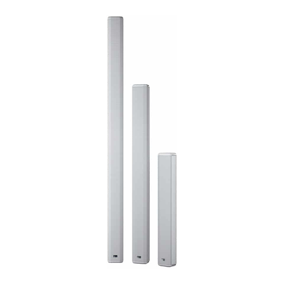
Updates and supplementary information are available at www.meyersound.com. Meyer Sound Technical Support is available at: Tel: +1 510 486.1166 • Tel: +1 510 486.0657 (after hours support) • Web: www.meyersound.com/support • CAL 96, CAL 64, and CAL 32 (Shown without Grille Frames) -
Page 10: Cal Installation Overview
Below is a basic overview for installing and using the CAL SPL of 106 dB at 90 meters with CAL 96—over an operating loudspeaker. Meyer Sound recommends that users read this frequency range of 100 Hz to 16 kHz. -
Page 11: Chapter 2: Power Requirements
CAL OPERATING INSTRUCTIONS CHAPTER 2: POWER REQUIREMENTS WIRING FOR AC CONNECTIONS CAL loudspeakers combine advanced loudspeaker technology with equally advanced power capabilities. CAL loudspeakers require a grounded outlet. To operate Understanding voltage and current requirements, as well as safely and effectively, it is extremely important that the electrical safety issues, is critical for safe operation of the entire system be properly grounded. -
Page 12: Cal Voltage Requirements
NOTE: When voltage fluctuates within CAL’s and may need to be serviced. Contact Meyer Sound rated voltage range, automatic tap selection Technical Support. stabilizes the operating voltage. This tap selection is instantaneous with no audible artifacts. -
Page 13: Electrical Safety Issues
Earth ground CAL Current Draw Current Draw Model 115 V AC 230 V AC 100 V AC Idle CAL 96 1.98 A rms 1.63 A rms 2.32 A rms CAL 64 1.24 A rms 0.99 A rms 1.42 A rms CAL 32 0.58 A rms... - Page 14 CHAPTER 2: POWER REQUIREMENTS...
-
Page 15: Chapter 3: Cal User Panel
CAL OPERATING INSTRUCTIONS CHAPTER 3: CAL USER PANEL AUDIO INPUT The CAL user panel includes audio input connectors, both analog and digital (AES/EBU), for receiving audio source CAL includes four numbered audio inputs: three analog and signals. It also includes logic connectors for selecting one digital. - Page 16 CHAPTER 3: CAL USER PANEL The positive (+) and negative (–) pins carry the input as a NOTE: Make sure that cabling for looped differential signal. The shield (S) pin is connected to earth loudspeakers is wired correctly (shield to through a 1 kOhm, 1000 pF, 15 V clamped network.
-
Page 17: On/Status Led
CAL OPERATING INSTRUCTIONS ON/STATUS LED CAL performs within its acoustical specifications when the Limit LEDs are unlit, or if the LEDs are lit for 2 seconds or less and then turn off for at least 1 second. If an LED Status remains lit for longer than 3 seconds, the loudspeaker enters hard limiting where:... -
Page 18: Logic I/O Ports
CHAPTER 3: CAL USER PANEL LOGIC I/O PORTS CAL Factory Presets A summary of the beam settings for the CAL factory presets The Logic I/O connectors provide a range of control and is shown in Table 2. CAL ships from the factory with these monitoring for CAL, including changing presets, overriding presets loaded into the loudspeaker. -
Page 19: Ethernet And Avb Ports
CAL OPERATING INSTRUCTIONS Override and Mute ETHERNET AND AVB PORTS Override Mute +5 Vdc Override and Mute Pins For installations where CAL is part of a fire alarm or evacuation system, the loudspeaker’s active audio input (main program source) can be muted or replaced with an Ethernet and AVB Ports override input (alarm or emergency announcement source). -
Page 20: Oled Button
CHAPTER 3: CAL USER PANEL OLED BUTTON USER PANEL COVER The OLED button is located in the upper right of the CAL A user panel cover is included with CAL to protect the user panel. During startup, the OLED displays the CAL connectors from dust in indoor installations and the loudspeaker’s Network port addresses. - Page 21 CAL OPERATING INSTRUCTIONS Removing and Installing the User Panel Cover To remove and install the user panel cover: 1. Use a screwdriver to remove the four pan head Phillips 10-32 x 0.75-inch screws, securing the user panel cover to the CAL loudspeaker. The four washers adhered to the user panel should remain in place.
- Page 22 CHAPTER 3: CAL USER PANEL...
-
Page 23: Chapter 4: Cal Coverage
Model Horizontal Vertical Vertical Vertical Fixed Beam Beam Beam Coverage Spread Angles Splits CAL 96 120° 5° to 30° (in 5° ±30° (in 1° Top, increments) increments) Bottom CAL 64 120° 5° to 30° (in 5° ±30° (in 1° Center... -
Page 24: Vertical Beam Angle
CHAPTER 4: CAL COVERAGE VERTICAL BEAM ANGLE VERTICAL BEAM SPREAD All CAL loudspeakers include vertical beam angles of ±30 All CAL loudspeakers include vertical beams with variable ° increments. The beams can also be of any supported spreads from 5 to 30 in 5 increments. -
Page 25: Vertical Beam Splits
[907 mm] 87.5° 35.69 [907 mm] Figure 1: Acoustical Center Points for CAL 32, CAL 64, and CAL 96 Figure 2: CAL 64 Center Split Beams with 5° Beam Spread NOTE: For the acoustical center points of beam split configurations, see “Vertical Beam... - Page 26 64 drivers. drivers and the bottom beam emanating from the bottom 32 Figure 3 shows a CAL 96 with top split beams, each with 5 drivers. Figure 4 shows a CAL 96 with bottom split beams, °...
-
Page 27: Chapter 5: Compass Control Software
The Beam Control tab displays CAL’s vertical beam spread and vertical beam angle, both of which can be altered by entering angle values or by dragging in the beam view area. Beam splits can also be configured on the Beam Control tab (CAL 64 and CAL 96 only). - Page 28 CHAPTER 5: COMPASS CONTROL SOFTWARE...
-
Page 29: Chapter 6: Mounting Cal Loudspeakers
When installing Meyer Sound loudspeakers, the following precautions should always be observed: Wall Mount 64.210.031.01 Plate (Black) (Use fasteners All Meyer Sound products must be used in accordance • (Bottom) 64.210.031.02 appropriate for with local, state, federal, and industry regulations. It is (White) wall material) the owner’s and user’s responsibility to evaluate the... -
Page 30: Mounting Cal Loudspeakers
(not included) appropriate for the wall material and rated to hold the weight of the loudspeaker. Bottom wall mount plate CAL 96 weight: 173 lbs (78.5 kg) NOTE: Orient the wall mount plates with the CAL 64 weight: 124 lbs (56.2 kg) side slots up. - Page 31 CAL OPERATING INSTRUCTIONS NOTE: Weights include top and bottom Attach the bottom loudspeaker bracket (the larger • loudspeaker brackets, top and bottom end one) to the bottom of the loudspeaker and secure it caps. with the included hex nut, lock washer, steel flat washer, nylon flat washer, and bushing.
- Page 32 5. Fully tighten the hex nuts securing the top and bottom screw hole of the bottom loudspeaker bracket (either loudspeaker brackets. Meyer Sound recommends side). The quick-release pin holds the loudspeaker in applying Loctite and using a torque value of 30 in-lb place.
-
Page 33: Single Point Hang Rigging Kit
8.00 in [203 mm] SINGLE POINT HANG RIGGING KIT 1.75 in 2.12 in [44 mm] Meyer Sound offers an optional single point hang rigging kit [54 mm] (PN 40.210.230.01) for applications where hanging a CAL loudspeaker is desirable. Front Right... -
Page 34: Installation Of Single Point Hang Kit
CHAPTER 6: MOUNTING CAL LOUDSPEAKERS INSTALLATION OF SINGLE POINT HANG KIT Installation Steps Please verify presence of all kit components (Table 1) before 1. Remove both screws and sealing washers from the beginning the install procedure. dress cap and set aside. Table 1: Single Point Hang Rigging Kit Contents Part Number Description... - Page 35 (40.5 N·m). CAUTION: There is one hole for the CAL 32 and the other is for CAL 64 or CAL 96. 5. Slide over the exposed threads in the order indicated: a. rubber gasket (PN 67.210.094.01), b. metal washer (PN 113.043).
- Page 36 (PN 119.061) removed in step 1. There are 2 extra washers included in the kit in case the original ones are damaged. Meyer Sound recommends applying the included Loctite and using a torque value of 22 in-lb (2.5 N·m).
-
Page 37: Appendix A: Cal Specifications
(196 ft or 60 m) duration, and 50°C ambient temperature) is <2 dB. M-noise is a full bandwidth (10 Hz to 22.5 kHz) test signal developed by Meyer Sound to CAL 32 better measure the loudspeaker’s music performance. It has a constant instantaneous... - Page 38 100–240 V AC, 50–60 Hz Turn-on and Turn-off Points 90 V AC turn-on; 264 V AC turn-off CURRENT DRAW Idle CAL 96 1.98 A rms (115 V AC) 1.63 A rms (230 V AC) 2.32 A rms (100 V AC) CAL 64 1.24 A rms (115 V AC)
- Page 39 Suitable for outdoor installations, rain hood included Rigging Adjustable brackets included for mounting on walls or columns Dimensions CAL 96 W: 7.75 in (197 mm) x H: 121.12 in (3076 mm) x D: 9.93 in (252 mm) (with mounting CAL 64 W: 7.75 in (197 mm) x H: 87.72 in (2228 mm) x D: 9.93 in (252 mm)
-
Page 40: Cal 96 Dimensions
APPENDIX A: CAL SPECIFICATIONS CAL 96 DIMENSIONS 6.01 [153 mm] 9.93 [252 mm] 7.75 [197 mm] 115.20 121.12 [2926 mm] [3076 mm] CAL 96 Dimensions (with Mounting Hardware) -
Page 41: Cal 64 Dimensions
CAL OPERATING INSTRUCTIONS CAL 64 DIMENSIONS 6.01 [153 mm] 9.93 [252 mm] 7.75 [197 mm] 81.80 87.72 [2078 mm] [2228 mm] CAL 64 Dimensions (with Mounting Hardware) -
Page 42: Cal 32 Dimensions
APPENDIX A: CAL SPECIFICATIONS CAL 32 DIMENSIONS 6.01 [153 mm] 9.93 [252 mm] 7.75 [197 mm] 48.40 54.32 [1229 mm] [1380 mm] CAL 32 Dimensions (with Mounting Hardware) - Page 44 Meyer Sound Laboratories Inc. 2832 San Pablo Avenue Berkeley, CA 94702 © 2012–2020 Meyer Sound Laboratories Inc. All rights reserved. www.meyersound.com CAL Operating Instructions PN 05.210.087.01 C2 T: +1 510 486.1166...
Need help?
Do you have a question about the CAL 96 and is the answer not in the manual?
Questions and answers