Moxa Technologies CP-134U User Manual
Industrial 4-port rs-422/485 serial board for universal pci bus
Hide thumbs
Also See for CP-134U:
- Quick installation manual (2 pages) ,
- User manual (141 pages) ,
- Quick installation manual (11 pages)
Table of Contents

Related Manuals for Moxa Technologies CP-134U


Summary of Contents for Moxa Technologies CP-134U
- Page 1 CP-134U Series User’s Manual Industrial 4-Port RS-422/485 Serial Board for Universal PCI Bus Twelfth Edition, June 2008 www.moxa.com/product © 2008 Moxa Inc., all rights reserved. Reproduction without permission is prohibited.
- Page 2 CP-134U Series User’s Manual The software described in this manual is furnished under a license agreement and may be used only in accordance with the terms of that agreement. Copyright Notice Copyright © 2008 Moxa Inc. All rights reserved. Reproduction without permission is prohibited.
-
Page 3: Table Of Contents
Features............................ 1-3 Package Checklist ........................1-3 Installation Flowchart ......................1-4 Chapter 2 Hardware Installation...................2-1 CP-134U Series Block Diagram ....................2-2 Jumper Settings........................2-4 DIP Switch Settings ......................... 2-5 Plugging the Board into an Expansion Slot ................2-7 Chapter 3 Software Installation ..................3-1 Windows Drivers ........................ - Page 4 PComm Programming Library ..................4-2 Utilities ............................ 4-2 Diagnostic (for Moxa boards only)................4-2 Monitor (for Moxa boards under Windows NT/2000/XP/2003) ........4-3 Terminal Emulator......................4-4 RS-485 Programming ......................4-5 ADDC™........................4-5 Chapter 5 Pin Assignments ..................5-1 Board Side Pin Assignments—Female DB44................5-2 RS-232 and RS-422 ......................
-
Page 5: Chapter 1 Introduction
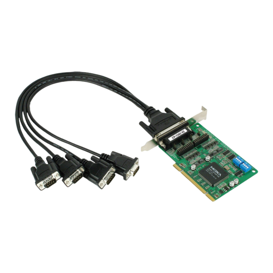
Introduction Chapter 1 Moxa’s CP-134U Universal PCI serial board meets the new slot standard for expansion boards, and works with both 3.3V and 5V PCI slots. The board has eight independent RS-232/422/485 serial ports for connecting data acquisition equipment and other serial devices to a PC. -
Page 6: Overview
“Technical Reference” appendix. Surge Protection The CP-134U series board comes with built-in 15 KV ESD surge protection to prevent damage to the board from lightning or high potential voltage. The surge protection feature makes the CP-134U board suitable for industrial, factory-type applications, and for use with applications that are subject to severe weather conditions. -
Page 7: Applications
CP-134U Series User’s Manual Introduction Applications The CP-134U series board is suitable for many different applications, including: Internet/Intranet Connections Remote Access Multi-user Applications Industrial Automation Office Automation Telecommunications PC-based Vending Machines and Kiosks POS (Point-of-Sale) Systems Features The CP-134U series board has the following outstanding features:... -
Page 8: Installation Flowchart
Installation Flowchart The following flowchart gives a brief summary of the procedure you should follow to install the CP-134U series board and which chapters to refer to for more detailed information: Use the onboard DIP Switches to select the Chapter 2, “Hardware Installation”... -
Page 9: Chapter 2 Hardware Installation
Chapter 2 The CP-134U series hardware installation procedure is described in this chapter. Since the CP-134U series board’s IRQ number and I/O addresses are assigned automatically by the PCI BIOS, the board MUST be plugged in before installing the driver. -
Page 10: Cp-134U Series Block Diagram
Hardware Installation CP-134U Series Block Diagram CP-134U Series boards’ IRQ number and I/O address are assigned automatically by the PCI BIOS. This means that the board MUST be plugged in first before installing the driver. CP-134U-I V2 (120 x 115 mm) 120 mm [4.72 in]... - Page 11 CP-134U Series User’s Manual Hardware Installation CP-134U V2 (120 x 82.5mm) 120 mm [4.72 in] 82.5mm [3.24 in] 4 WIRE RS422 101 mm [3.97 in] MU860 121 mm [4.76 in] 41.7 mm [1.64 in] CP-134U V1 (135 x110mm) 135.0 mm (5.31 in) NOTE: Use JP1/2/3/4 to activate the Termination Resistors for ports 1/2/3/4.
-
Page 12: Jumper Settings
Hardware Installation The CP-134U series has two 30-pin jumpers and two sets of four DIP Switches on the board that allow the user to set the serial interface for each of the board’s four ports. Ports 1 and 2 can be set to RS-232, RS-422, RS-485 (2-wire), or RS-485 (4-wire). -
Page 13: Dip Switch Settings
CP-134U Series User’s Manual Hardware Installation DIP Switch Settings Refer to the figures on the following two pages to see how to select between RS-422, RS-485 (2-wire), and RS-485 (4-wire). Port 1 DIP Switch Settings S1-1 S2-1 RS-232 — —... - Page 14 CP-134U Series User’s Manual Hardware Installation Port 3 DIP Switch Settings S1-3 S2-3 2-WIRE RS485 ON DIP ON DIP RS-422 — 4-WIRE RS422 2-WIRE RS485 ON DIP ON DIP RS-485 (2-wire) 4-WIRE RS422 2-WIRE RS485 ON DIP ON DIP RS-485...
-
Page 15: Plugging The Board Into An Expansion Slot
Hardware Installation Plugging the Board into an Expansion Slot Since the CP-134U series board’s IRQ number and I/O address are automatically assigned by the PCI BIOS, the board MUST be plugged into one of the computer’s expansion slots before installing the driver. -
Page 17: Chapter 3 Software Installation
Refer to the next chapter, “Serial Programming Tools,” for information about developing your own serial programming applications. Note that up to 4 CP-134U boards can be installed in one system, provided sufficient I/O address and IRQ number resources are available. -
Page 18: Windows Drivers
Moxa provides drivers that allow you to use the following serial board products under Windows 2003/XP/2000, Windows XP Embedded, Windows 98/95, and Windows NT. Universal PCI Boards: CP-168U, CP-104UL, CP-104JU, CP-134U, CP-134U-I, CP-132UL, CP-132UL-I V2(CP-132U-I V1) PCI Boards: C168H/PCI, C104H/PCI, C104HS/PCI, CP-114, CP-114I, CP-114S, CP-114IS,... -
Page 19: Windows 2003/Xp
COMM API standard. Installing the Driver The following procedure shows how to install the CP-134U driver for the first time under Windows XP. First, make sure the board or boards have already been plugged into the system’s PCI or PCI-X slot(s). - Page 20 Software Installation Select Search for the best driver in these locations, check Include this location in the search, and then click on Browse. Navigate to the \CP-134U\Software\Win2K-XP-2003 folder on the software CD, and then click on Next to continue. Wait while the installation wizard searches. The next window that opens cautions you that although this software hasn’t passed Windows Logo testing, the driver has been tested and...
- Page 21 CP-134U Series User’s Manual Software Installation Wait while the driver software is installed. The next window shows the model name of the board, and indicates that Windows has completed the driver installation. Click on Finish to proceed with the rest of the installation...
- Page 22 Select Search for the best driver in these locations, check Include this location in the search, and then click on Browse. If necessary, use the Browse button to navigate to the CP-134U\Software\Win2K-XP-2003 folder, and then click on Next to proceed.
- Page 23 CP-134U Series User’s Manual Software Installation Wait while the installation wizard searches. The next window that opens cautions you that although this software hasn’t passed Windows Logo testing, the driver has been tested and shown that it can support the Windows OS. Click on Continue Anyway to proceed.
- Page 24 CP-134U Series User’s Manual Software Installation 11. After all files have been copied to the system, the Completing the Found New Hardware Wizard window will open to indicate that it has finished installing Port 0. Click on Finish to proceed with the rest of the installation.
-
Page 25: Configuring The Ports
13. The Found New Hardware pop-up window will reappear to inform you that the hardware was installed successfully. Configuring the Ports After the driver has been installed, use Device Manager to configure the CP-134U serial ports. Click on Start System, select the Hardware tab, and then... - Page 26 CP-134U Series User’s Manual Software Installation Expand the Multi-port serial adapters tab, right click on Moxa CP-134U Series (PCI Bus), and then click on Properties to open the board’s configuration panel. Click on the port you would like to configure to highlight it, and then click on Port Setting.
-
Page 27: Using Moxa Pcomm Utility
CP-134U Series User’s Manual Software Installation Select a COM number for the port from the Port Number pull-down list. Check the Auto Enumerating COM Number checkbox to map subsequent ports automatically. The port numbers will be assigned in sequence. For example, if COM 3 is assigned to Port 1, then COM 4 (if not already occupied) will be assigned to Port 2, etc. -
Page 28: Using Event Log
System, select the Settings Control Panel Hardware tab, and then click on Device Manager. Use the mouse to place the cursor over the CP-134U Series board under Multi-port serial adapters, and then click the right mouse button. Select the Uninstall… option. 3-12... - Page 29 CP-134U Series User’s Manual Software Installation Click on OK to proceed with uninstalling the board. 3-13...
-
Page 30: Windows 2000
COMM API standard. Installing the Driver for the First Time The following procedure shows how to install the CP-134U driver for the first time under Windows 2000. First, make sure the board or boards have already been plugged into the system’s PCI or PCI-X slot(s). - Page 31 CP-134U Series User’s Manual Software Installation After plugging the board into an expansion slot and powering on your PC, Windows 2000 will automatically detect the new board, and the Found New Hardware window will open. When the Welcome to the Found New Hardware Wizard window opens, click on Next to continue.
- Page 32 CP-134U Series User’s Manual Software Installation Select Search for a suitable driver for my device (recommended), and then click on Next to continue. Select Specify a location and then click on Next to continue. 3-16...
- Page 33 CP-134U Series User’s Manual Software Installation Navigate to the \CP-134U\Software\Win2K-XP-2003 folder on the software CD, and then click on OK to continue. Click on Next to copy the driver files to your system. 3-17...
- Page 34 CP-134U Series User’s Manual Software Installation Wait while the installation wizard searches. The next window that opens cautions you that although this software hasn’t passed Windows Logo testing, the driver has been tested and shown that it can support the Windows OS. Click on Yes to proceed.
-
Page 35: Configuring The Ports
Configuring the Ports After the driver has been installed, use Device Manager to configure the CP-134U serial ports. Click on Start System, select the Hardware tab, and then... - Page 36 CP-134U Series User’s Manual Software Installation Expand the Multi-port serial adapters tab, right click on Moxa CP-134U Series (PCI Bus), and then click on Properties to open the board’s configuration panel. 3-20...
- Page 37 CP-134U Series User’s Manual Software Installation Basic information about the board is displayed on the General page. Click on the Ports Configuration tab to configure the board’s serial ports. Click on the port you would like to configure to highlight it, and then click on Port Setting.
-
Page 38: Using Moxa Pcomm Utility
CP-134U Series User’s Manual Software Installation Select a COM number for the port from the Port Number pull-down list. Check the Auto Enumerating COM Number checkbox to map subsequent ports automatically. The port numbers will be assigned in sequence. For example, if COM 3 is assigned to Port 1, then COM 4 (if not already occupied) will be assigned to Port 2, etc. -
Page 39: Using Event Log
System, select the Settings Control Panel Hardware tab, and then click on Device Manager. Use the mouse to place the cursor over the CP-134U Series board under Multi-port serial adapters, and then click the right mouse button. Select the Uninstall… option. 3-23... - Page 40 CP-134U Series User’s Manual Software Installation Click on OK to proceed with uninstalling the board. 3-24...
-
Page 41: Windows 95/98
Win32 COMM API standard. Installing the Driver for the First Time The following procedure shows how to install the CP-134U driver for the first time under Windows 98. First, make sure the board or boards have already been plugged into the system’s PCI or PCI-X slot(s). - Page 42 CP-134U Series User’s Manual Software Installation After plugging the board into an expansion slot and powering on your PC, Windows 98 will automatically detect the new board, and display the Found New Hardware window. When the Add New Hardware Wizard window opens, click on Next to continue.
- Page 43 CP-134U Series User’s Manual Software Installation Select Other Devices and then click on Next to proceed. Click on Have Disk. Use the Browse button to navigate to the \CP-134U\Software\Win9x\Windows.95 folder on the Documentation and Software CD, and then click on OK. 3-27...
- Page 44 CP-134U Series User’s Manual Software Installation Click on CP-134U Series [8-23-2004] to highlight it, and then click on Next. Verify that the CP-134U Series driver will be installed, and then click on Next. 3-28...
- Page 45 Basic configuration information will be displayed in the CP-134U Series Installation window. Click on OK to complete the installation of the board. This completes the installation of the CP-134U board. Click on Finish to exit the Add New Hardware Wizard.
-
Page 46: Configuring The Ports
Follow the procedures given below to re-configure the board’s COM ports. Since CP-134U is a Universal PCI board, when a new board is added or an existing board is removed, the board’s configuration will be added or removed automatically by the operating system when you restart the PC. - Page 47 CP-134U Series User’s Manual Software Installation Basic information about the board is displayed on the General page. Click on the Ports Configuration tab to configure the board’s serial ports. Click on the port you would like to configure to highlight it, and then click on Port Setting.
-
Page 48: Updating The Driver
This section explains how to update the Windows 98 driver. Open the Control Panel, click on the System icon, and select the Device Manager tab. Click on a Moxa CP-134U board under Moxa Smartio/Industio multiport board to highlight it, and then click on Properties. - Page 49 CP-134U Series User’s Manual Software Installation Select the Driver tab, and click on Update Driver…. 3-33...
- Page 50 CP-134U Series User’s Manual Software Installation Click on Next. Select Display a list of all the drivers in a specific location, so you can select the driver you want., and then click on Next. 3-34...
-
Page 51: Removing The Driver
CP-134U Series User’s Manual Software Installation In the next window, the CP-134U Series option should already be highlighted. Click on Have Disk… and then navigate to the folder that contains the new driver file. Follow the on-screen instructions to complete the driver update procedure. - Page 52 CP-134U Series User’s Manual Software Installation Click on Yes to confirm that you want to remove the driver. Click on OK. 3-36...
-
Page 53: Windows Nt
Windows NT supports up to 256 serial ports, from COM1 to COM256. To utilize fully Windows NT’s multi-process and multi-thread advanced features, pure 32-bit Windows NT device drivers were developed for the CP-134U boards and other Moxa multiport boards. The drivers conform to the Win32 COMM API standard. - Page 54 CP-134U Series User’s Manual Software Installation elect Moxa Smartio/Industio Family multiport board in the Select OEM Option window, and then click on OK to start installing the driver. The Moxa Smartio/Industio Configuration Panel window appears. Click on Add to open the Property configuration window to change port settings and set advanced FIFO configuration options.
-
Page 55: Configuring The Ports
Configuring the Ports Follow the instructions in this subsection if the CP-134U Windows NT driver is already installed, and you wish to re-configure a board’s ports or configure the ports of a newly installed board. In addition to the procedures listed below, you may also click on Start... - Page 56 CP-134U Series User’s Manual Software Installation Select the just installed CP-134U board from the Board Type pull-down list, click on a specific port to highlight it, and then click on Port Setting to configure the port. Select a COM number for the port from the Port Number pull-down list.
- Page 57 Click on OK to save the settings, and then click on OK in the Property window to complete the port settings and return to the Moxa Smartio/Industio Configuration Panel window. The just configured CP-134U board will be listed, as shown below. Click on OK to return to the Network window.
-
Page 58: Using Event Log
To view the event log, enter the Administrative grou p, click the Event Viewer icon, and then select Log and System to check a message similar to “Moxa CP-134U board, with first serial po COM3, has been enabled” for each newly configured board. -
Page 59: Removing A Cp-134U Board
Software Installation Removing a CP-134U Board To remove a CP-134U board, first sh ut down your PC, and then physically remove the board from the PCI or PCI-X slot. The next time you start up the PC, the system will automatically remove the configuration for the board. -
Page 60: Non-Windows Drivers
Moxa provides drivers that allow you to use the following serial board products under DOS: Universal PCI Boards: CP-118U, CP-168U, CP-104UL, CP-104JU, CP-102U, CP-102 CP-134U, CP-134U-I, CP-132UL, CP-132UL-I V2(CP-132U-I V1) PCI Boards: C168H/PCI, C104H/PCI, C104HS/PCI, CP-114, CP-114I, CP-114S, CP-114IS CP-132, CP-132I, CP-132S, CP-132IS... -
Page 61: Setting Up The Driver
CP-134U Series User’s Manual Software Installation Setting up the Driver This sect ion covers some of the setup program’s most frequently used functions. For complete details, press F1 to open the on-line help file. Run BIN\SETUP.EXE. Press Enter to select the model name of th e Moxa board you are installing. -
Page 62: Legends
CP-134U Series User’s Manual Software Installation ou may enter or modify the settings of each port at this stage. The values displayed first are e port’s initial values that were set up when the driver was installed. Press F10 to save the changes and exit the SETUP program. -
Page 63: Loading The Driver
CP-134U series (Bus= x ,Dev=y) : OK! Device driver setup O.K. This means that the CP-134U Series driver has been installed properly. At this point, you may execute applications that support API-232 functions, or start developing applications using the API-232 library. - Page 64 = Moxa Smartio/Industio Family Multiport Board Status Utility(1.1)= Tty Device Major Number= 30. Callout device Major Number= 35. Board 1 : CP-134U series (BusNo=2, DevNo=13) Port 1: 0xac00, max. baud rate = 230400 bps. Port 2: 0xac08, max. baud rate = 230400 bps.
-
Page 65: Chapter 4 Serial Programming Tools
Serial Programming Tools Chapter 4 Moxa provides an easy to use yet powerful serial programming library, and communication troubleshooting utilities under Windows 2000/XP/2003, Windows 95/98, and Windows NT. The following sections give details about the installation, the library, and the utilities for various platforms. -
Page 66: Moxa Pcomm
CP-134U Series User’s Manual Serial Programming Tools Moxa PComm PComm, a professional serial comm tool for PCs, is a software package that runs under Windows NT/2000/XP/2003/95/98. PComm provides: A powerful serial communication library that simplifies serial programming tasks for most popular programming languages. -
Page 67: Monitor (For Moxa Boards Under Windows Nt/2000/Xp/2003)
CP-134U Series User’s Manual Serial Programming Tools Monitor (for Moxa boards under Windows NT/2000/XP/2003) This useful port status monitoring program allows you to monitor data transmission of selected Moxa COM ports. The program monitors data transmission/receiving throughput, and communication line status, with data updated and displayed on the screen at regular time intervals. -
Page 68: Terminal Emulator
CP-134U Series User’s Manual Serial Programming Tools Terminal Emulator Use Terminal Emulator to connect to your PC’s serial ports to check if data is being transmitted correctly. Terminal Emulator features multi-windows, and supports VT100 and ANSI terminal types. You can transfer data interactively, send patterns periodically, and transfer files using ASCII, XMODEM, YMODEM, ZMODEM, and KERMIT protocols. -
Page 69: Rs-485 Programming
Serial Programming Tools RS-485 Programming If you are using your CP-134U Series board for RS-485 applications, in addition to reading this section, you should also refer to the “Connection Cables and Cable Wiring” chapter for more details about using RS-485. -
Page 71: Chapter 5 Pin Assignments
A maximum of 32 drivers and 32 receivers can be set up on a multidrop network. The CP-134U board supports both 2-wire half-duplex and 4-wire full-duplex RS-485 communications. In 2-wire RS-485, Data+/- pins are used for both data transmitting and receiving. -
Page 72: Board Side Pin Assignments-Female Db44
A maximum of 32 drivers and 32 receivers can be set up on a multidrop network. The CP-134U Series supports both 2-wire half-duplex and 4-wire full-duplex RS-485 communications. In 2-wire RS-485, Data+/- pins are used for both data transmitting and receiving,... -
Page 73: Device Side Pin Assignments
CP-134U Series User’s Manual Pin Assignments 41 43 1 3 5 7 9 11 13 15 Port 4 Port 3 Port 2 Port 1 CP-134U (4-wire RS-485) CP-134U (2-wire RS-485) Port 1 Port 2 Port 3 Port 4 Port 1... -
Page 74: Male Db25
CP-134U Series User’s Manual Pin Assignments Male DB25 RS-422 / RS-232 2-wire RS-485 4-wire RS-485 RxD+(B) Data+(B) TxD+(B) TxD-(A) RxD-(A) Data-(A) Female DB25 RS-422 / RS-232 2-wire RS-485 4-wire RS-485 TxD+(B) RxD+(B) Data+(B) RxD-(A) Data-(A) TxD-(A) -
Page 75: Rj45
RxD-(A) RxD+(B) TxD+(B) RxD+(B) TxD+(B) TxD-(A) RxD-(A) RxD-(A) TxD-(A) RxD-(A) TxD-(A) RS-422 Device N RxD+(B) TxD+(B) RxD-(A) TxD-(A) CP-134U – RS-422 with Handshaking CP-134U RS-422 Device TxD+(B) RxD+(B) TxD-(A) RxD-(A) RxD+(B) TxD+(B) RxD-(A) TxD-(A) RTS+(B) CTS+(B) RTS-(A) CTS-(A) CTS+(B) RTS+(B) -
Page 76: Impedance Matching And Termination Resistors
CP-134U Series User’s Manual Pin Assignments CP-134U – 2-wire RS-485 CP-134U RS-485 Device Data+(B) Data+(B) Data-(A) Data-(A) Multidrop 2-wire RS-485 (half-duplex) CP-134U RS-485 Device 1 Master Slave Data+ Data+ Data- Data- RS-485 Device N Slave Data+ Data- Multidrop 4-wire RS-485 (full-duplex) -
Page 77: Chapter 6 Troubleshooting
32-bit PCI slot. It is also possible that a slot has malfunctioned. In this case, try other slots until you find one that works. The motherboard does not have an available IRQ for the CP-134U Series board. In this case, enter the BIOS and make sure there is an available IRQ under PCI/PnP settings. -
Page 78: Windows Nt
The slot the boards are plugged into is defective. Try another slot until you find one that works. The board might be defective. After the system reboots, the error message “CP-134U Series (BusNo=x, DevNo=x, Port1=COMx) interrupt number is invalid!” appears. This indicates that the Moxa board was found, but the IRQ conflicts with another adapter. -
Page 79: Appendix A Technical Reference
Assigned by PCI BIOS Comm. controller Moxa UART (16C550C compatible) Transmission speed 50 bps to 230.4 Kbps (CP-134U, CP-134U-I) 50 bps to 921.6 Kbps (CP-134U V2, CP-134U-I V2) Data bits 5, 6, 7, 8 Stop bits 1, 1.5, 2 Parity... -
Page 80: Pci
Due to slot-dependency, it is necessary to re-configure the driver software once the board is plugged into different PCI slots. Up to 4 CP-134U Series boards are allowed in one system. When installing more than one board, remember the order the boards are installed to distinguish the installed boards from each other.
Need help?
Do you have a question about the CP-134U and is the answer not in the manual?
Questions and answers