Moxa Technologies CP-114UL Series Quick Installation Manual
Universal pci smart serial board
Hide thumbs
Also See for CP-114UL Series:
- Quick installation manual (2 pages) ,
- User manual (141 pages) ,
- Quick installation manual (11 pages)
Advertisement
Universal PCI Smart Serial Board
Quick Installation Guide
First Edition, October 2017
Overview
Moxa's Universal PCI (UPCI) multiport serial boards can be
installed in PCI or PCI-X slots and support both 3.3V and 5V
PCI/PCI-X.
Package Checklist
UFCI board are shipped with the following items:
•
1 Moxa UPCI multiport serial board
Low-profile bracket (low-profile models only)
•
Documentation and software CD
•
Quick installation guide (printed)
•
•
Warranty card
NOTE Notify your sales representative if any of the above items
are missing or damaged.
Hardware Installation Procedure
The Universal PCI board MUST be plugged into the PC before the
driver is installed.
Follow the steps below:
1. Select serial transmission mode. This step is for certain
models listed below.If your product on hand is not included,
please directly go to step2.
If your model is CP-112UL Series/ CP-114UL Series / CP-118U
Series/ CP-132UL Series/ CP-134U Series/ CP-138U Series,
you will need to set onboard DIP switches for each port.
(Refer to "Dip Switch Settings" section to complete the DIP
switches setting)
2. Install the board. Power off the PC and then plug the board
firmly into any open PCI or PCI-X expansion slot.
3. Plug the connection cable into the board's connector.
(Refer to "Pin Assignments" section for the cable pin
assignment).
4. Start system and verify the driver initialization.
P/N: 1802001142325
– 1 –
Software Installation Information
1. Get the driver at
www.moxa.com
or from the CD. Based
on the OS type, choose the corresponding driver.
2. Installing the driver:
•
For Windows OS (Take the installation of Win7 as
an example)
o
2.1. Unzip and execute the .exe file
o
2.2. Follow the instructions to install the
drivers
For Linux
•
Execute the following commands from the Linux
prompt:
o
2.1. Get the driver from CD and Unzip the
file:
#mount /dev/cdrom /mnt/cdrom
#cd /
#mkdir moxa
#cd moxa
#cp /mnt/cdrom/<driver
directory>/mxser.tgz .
#tar xvfz mxser.tgz
o
2.2. Install the driver:
#cd mxser
#./mxinstall
o
2.3. Verify the driver status
Use the Moxa diagnostic utility to verify
the driver status:
#cd /moxa/mxser/utility/diag
#./msdiag
o
2.4. Test the tty port
Use the Moxa terminal utility to test the
tty ports:
#cd /moxa/mxser/utility/term
#./msterm
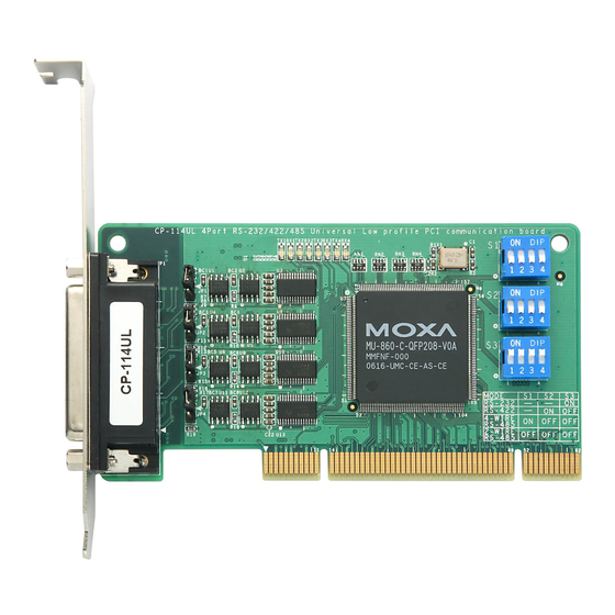
DIP Switch Settings
CP-112UL Series /CP-112UL-I Series
Mode
S1
S2
RS-232
ON
-
RS-422
OFF
ON
4-Wire RS-485
OFF
OFF
2-Wire RS-485
OFF
OFF
– 2 –
CP-114UL Series /CP-114UL-I Series
Mode
RS-232
RS-422
4-Wire RS-485
2-Wire RS-485
CP-118U Series /CP-118U-I Series
Mode
RS-232
RS-422
4-Wire RS-485
2-Wire RS-485
CP-132UL Series
Mode
RS-422
2-Wire RS-485
4-Wire RS-485
CP-134U Series /CP-134U-I Series
S3
-
-
ON
OFF
RS-422 or RS-485 mode:
Use the jumper to cover the
two columns on the left of the
jumper pins.
S1
S2
S3
-
-
ON
-
ON
OFF
ON
OFF
OFF
OFF
OFF
OFF
S1
S2
S3
-
-
ON
ON
OFF
ON
OFF
OFF
OFF
OFF
OFF
S1
S2
Illustration
-
OFF
ON
ON
OFF
ONN
RS-232 mode: Use the
jumper to cover the two
columns on the right of the
jumper pins.
– 3 –
Advertisement
Table of Contents

Related Manuals for Moxa Technologies CP-114UL Series


Summary of Contents for Moxa Technologies CP-114UL Series
-
Page 1: Quick Installation Guide
1. Select serial transmission mode. This step is for certain models listed below.If your product on hand is not included, CP-112UL Series /CP-112UL-I Series please directly go to step2. If your model is CP-112UL Series/ CP-114UL Series / CP-118U Mode Series/ CP-132UL Series/ CP-134U Series/ CP-138U Series, RS-232 you will need to set onboard DIP switches for each port. - Page 2 TxD+(B) – RxD+(B) Data+(B) RxD-(A) Data+(A) CP-102UL Series – Female DB25 RS-232 Signal Signal (CBL-M44M9x4-50) DCD1 DTR1 (Opt4-M9A) CP-114UL Series DSR1 Pin RS-232 Male DB9 (CBL-M44M9x4-50) CTS1 RTS1 RxD1 TxD1 Pin RS-232 RS-422/485-4W RS-485-2W TxD-(A) – – TxD+(B) – DCD0...
- Page 3 Male DB25 (CBL-M44M25x4-50) RJ45 (opt8-RJ45) CP-118U Series/CP-138U Series Pin RS-232 RS-422/ RS-485-2W Pin Signal* RS-485-4W Male DB9 RxD+(B) Data+(B) (CBL-M62M9x8-100, Opt8-M9 is for CP-118U and CP-138U) TxD+(B) – (CBL-M78M9x8-100 is for CP-118U-I and CP-138U-I) – – Pin RS-232 RS-422/ RS-485-2W –...
- Page 4 OPT8-RJ45 (8-pin) RS-422/485 Cable Wiring for Opt8K CP-134U Series Pin Signal RS-422/ RS-485-2W Male DB9 (CBL-M44M9x4-50) RS-485-4W Pin Signal Pin Signal Pin RS-232 RS-422/ RS-485- RS-485- RxD+(B) Data+(B) TxD+(B) 14 Data-(A) TxD-(A) TxD-(A) – 14 RxD-(A) TxD+(B) TxD+(B) – 16 TxD-(A) RxD+(B) RxD+(B) Data +(B)
Need help?
Do you have a question about the CP-114UL Series and is the answer not in the manual?
Questions and answers