Moxa Technologies CP-134U Quick Installation Manual
Smart serial board
Hide thumbs
Also See for CP-134U:
- User manual (80 pages) ,
- Quick installation manual (2 pages) ,
- User manual (141 pages)
Advertisement
Quick Links
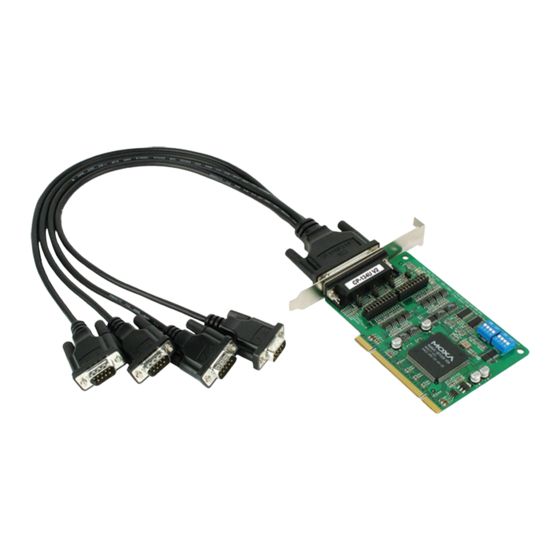
CP-134U Smart Serial Board
Quick Installation Guide
Fifth Edition, June 2008
1. Overview
Moxa's CP-134U Series of Smart Multiport Serial Boards provides
Industrial Automation system integrators with long transmission
distance, multi-point, PC-based data acquisition solutions. Powered by
Moxa's Turbo Serial Engine™ chip that comes with on-chip ADDC™
(Automatic Data Direction Control), sending RS-485 packets is as easy
as using RS-232. The on-chip ADDC™ feature delivers precise timing
control for enabling and disabling the line drivers used for 2-wire
RS-485 communication.
When configured for RS-422/485, each of CP-134U's 4 serial ports can
transmit at up to 921.6 Kbps, and each RS-485 port can support up to
31 daisy-chained serial devices in a 1.2 km multi-drop environment. To
help prevent equipment damage when using long distance RS-485
communication, choose CP-134U-I, which provides isolation
protection against voltage mismatches of up to 2 KV.
CP-134U is a MOXA Green Product. Moxa's Green Products satisfy
the RoHS directive of the European Parliament, and accordingly, do
not contain cadmium and cadmium compounds, hexavalent chromium
compounds, lead and lead compounds, mercury and mercury
compounds, PBBs (polybrominated biphenyls), or PBDEs
(polybrominated diphenyl ethers).
2. Package Checklist
Before installing the CP-134U board, verify that the package contains
the following items:
1 CP-134U 4-port serial board
Documentation and Software CD, which contains drivers for
Windows 2000/XP/2003, Windows NT, Windows 95/98,
DOS, FreeBSD, and Linux.
CP-134U Quick Installation Guide
Notify your sales representative if any of the above items is missing or
damaged.
3. Hardware Installation Procedure
The CP-134U board MUST be plugged into the PC before the driver is
installed. Follow these steps to install the board in the PC.
STEP 1: Power off the PC.
STEP 2: Plug the CP-134U control board firmly into an open 32-bit or
64-bit PCI slot.
— 1 —
STEP 3: Use the on-board jumpers and DIP switches to set the serial
ports for RS-232, RS-422, or 2-/4-wire RS-485.*
STEP 4: Fasten the holding screw to fix the control board in place.
STEP 5: Power on the PC; the BIOS will automatically set the IRQ and
I/O address.
* Use the 30-pin jumper arrays and 2 DIP switches to set ports 1 and 2
to RS-232, RS-422, or RS-485, and use the 2 DIP switches to set ports
3 and 4 to RS-422 or RS-485. Jumper and DIP switch settings are given
in the following table.
Jumper and DIP Switch Settings
Serial
Interface
RS-232
RS-422
2w RS-485
4w RS-485
NOTE: N/A = Not Active. Ports 3 and 4 do not support RS-232.
The following figures illustrate the DIP switch settings for Port 1.
2-WIRE
S1
ON DIP
1
2
3
4
4-WIRE
2-WIRE
S1
ON DIP
1
2
3
4
4-WIRE
2-WIRE
S1
ON DIP
1
2
3
4
4-WIRE
4. Software Installation Information
The board MUST be plugged in before installing the driver. See the
previous section for instructions on how to install the board in your PC.
Refer to the CP-134U User's Manual for detailed instructions on
installing the drivers for this board.
Windows 2003/XP Driver Installation
1. After powering on your PC, Windows 2003/XP will automatically
detect the CP-134U board.
2. Insert the CP-134U software CD in your CD-ROM drive.
P/N: 1802001340300
Jumper
Ports 1 and 2
Ports 3 and 4
Placement
S1
S2
S1
on right
N/A
N/A
---
on left
N/A
OFF
N/A
on left
ON
ON
ON
on left
OFF
ON
OFF
RS485
S2
ON DIP
Port 1 set for RS-422 transmission.
1
2
3
4
RS422
RS485
S2
ON DIP
Port 1 set for 2-wire RS-485 transmission.
1
2
3
4
RS422
RS485
S2
ON DIP
Port 1 set for 4-wire RS-485 transmission.
1
2
3
4
RS422
— 2 —
3. Select Install from a list or specific location (Advanced).
4. After selecting Search for the best driver in these locations, check
the Include this location in the search checkbox, and then use the
browse button to navigate to the CD's
CP-134U v2\Software\Win2K-XP-2003 folder.
5. Click on Continue Anyway in response to any warnings that the
software hasn't passed Windows Logo testing.
6. After the board has been installed, the installation wizard will guide
you through the port installation procedure, starting with port 0.
7. If the board appears to be installed incorrectly, use the Device
Manager to check the installation of the board and ports. Click on the
+ sign next to Hardware, and then check under Multi-port serial
adapters and Ports (COM & LPT). If there are no warning marks,
such as a question mark or exclamation point in front of the board or
S2
port icons, examine the Event Log to determine what the problem is.
---
Windows 2000 Driver Installation
OFF
1. After powering on your PC, Windows 2000 will automatically detect
ON
the CP-134U board.
ON
2. Insert the CP-134U software CD in your CD-ROM drive.
3. Select Search for a suitable driver for my device (recommended).
4. In Optional search location, checkmark specify a location. Navigate
to the \CP-134U \Software\Win2K-XP-2003 folder on the software
CD, and then click on OK to continue.
5. Click on Continue Anyway in response to any warnings that the
software hasn't passed Windows Logo testing.
6. After the board has been installed, the installation wizard will guide
you through the port installation procedure, starting with port 0.
7. If the board appears to be installed incorrectly, use the Device
Manager to check the installation of the board and ports. Click on the
+ sign next to Hardware, and then check under Multi-port serial
adapters and Ports (COM & LPT). If there are no warning marks,
such as a question mark or exclamation point in front of the board or
port icons, examine the Event Log to determine what the problem is.
Windows 95/98 Driver Installation
1. After powering on your PC, Windows 95/98 will automatically detect
the CP-134U board.
2. Insert the CP-134U software CD in your CD-ROM drive.
3. There are some differences between the installation procedures for
Windows 95 and Windows 98. However, in both cases, be sure to
install the driver from the CD's
CP-134U v2\Software\Win9x\Windows.95 folder.
4. After the board has been installed, the installation wizard will open
the port configuration window.
NOTE: If an error message similar to "CP-134U board (BusNo=x,
DevNo=x, Port1=COMx) interrupt number is invalid!" pops up, refer
to the "Troubleshooting" chapter of the User's Manual for
information on how to handle this error.
— 3 —
Advertisement

Related Manuals for Moxa Technologies CP-134U


Summary of Contents for Moxa Technologies CP-134U
- Page 1 4. After the board has been installed, the installation wizard will open the port configuration window. The CP-134U board MUST be plugged into the PC before the driver is Windows 2003/XP Driver Installation NOTE: If an error message similar to “CP-134U board (BusNo=x, installed.
- Page 2 TxD-(A) 5. Pin Assignments P4: CTS-(A) RxD-(A) RxD-(A) Data-(A) The CP-134U boards have a female DB44 connector on the board. In P4: GND P4: GND CTS-(A) this section, we give the on-board connector’s pin assignments to P3: TxD-(A) P3: TxD-(A)
Need help?
Do you have a question about the CP-134U and is the answer not in the manual?
Questions and answers