Moxa Technologies CP-118U User Manual
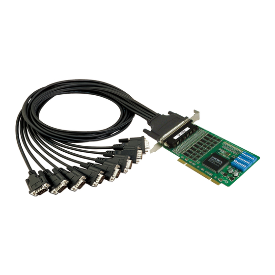
Universal pci board
Hide thumbs
Also See for CP-118U:
- User manual (131 pages) ,
- Quick installation manual (2 pages) ,
- User manual (84 pages)

Related Manuals for Moxa Technologies CP-118U


Summary of Contents for Moxa Technologies CP-118U
- Page 1 Universal PCI Board User’s Manual Multiport Serial Board for PCI and PCI-X Bus Edition 12.0, October 2017 www.moxa.com/product © 2017 Moxa Inc. All rights reserved.
- Page 2 Universal PCI Board User’s Manual The software described in this manual is furnished under a license agreement and may be used only in accordance with the terms of that agreement. Copyright Notice © 2017 Moxa Inc. All rights reserved. Trademarks The MOXA logo is a registered trademark of Moxa Inc.
-
Page 3: Table Of Contents
Product Features ..........................1-5 Product Specifications ......................... 1-5 Installation Guide ..........................1-7 Hardware Installation ........................2-1 Overview ............................2-2 Configuring the Board and Dimension ....................2-2 CP-118U/CP-118U-I........................2-2 CP-138U/CP-138U-I........................2-3 CP-168U ............................ 2-5 CP-114UL/CP-114UL-I ......................... 2-5 CP-134U/CP-134U-I........................2-7 CP-104UL ........................... 2-8 CP-104JU ........................... - Page 4 DB44 (Female): RS-232 ....................... 6-7 DB44 (Female): RS-422, RS-485 (4-wire) ..................6-7 DB44 (Female): RS-485 (2-wire)....................6-8 CP-118U ............................6-8 DB62 (Female): RS-232 ....................... 6-9 DB62 (Female): RS-422, RS-485 (4-wire) ..................6-9 DB62 (Female): RS-485 (2-wire)....................6-10 CP-118U-I ............................6-11 DB78 (Female): RS-232 ......................
-
Page 5: Introduction
Introduction The following topics are covered in this chapter: Overview Applications Package Checklist Product Features Product Specifications Installation Guide... -
Page 6: Overview
128-byte Tx/Rx FIFO, and well-designed device drivers that have been fine-tuned. This allows Moxa UPCI boards to support data transmission speeds of up to 921.6 Kbps. The following UPCI multiport serial boards are available from Moxa: 8 Ports CP-118U: 8 ports, RS-232/422/485 CP-118U-T: 8 ports, RS-232/422/485, wide temperature... -
Page 7: Universal Pci
Industio—The Industrial Multiport Async Solution The Industio Series of multiport serial boards includes the CP-118U-I, CP-118U, CP-138U-I, CP-138U, CP-114UL, CP134U, CP-134U-I, CP-132UL, and CP-132UL-I. These boards are designed for industrial use, with serial ports that can be configured independently for RS-232, RS-422, or RS-485 operation. Industio boards provide a reliable communication link over distances of up to 4000 ft and support point-to-point full-duplex or multi-drop half-duplex. -
Page 8: Applications
Universal PCI Board Introduction Applications UPCI boards are suitable for many industrial applications, including the following: • Multipoint data acquisition • Factory automation • Critical industrial control • Remote serial device control • Internet/intranet connections • Remote access applications • Multi-user applications •... -
Page 9: Product Features
2 KV optical isolation protection (on “I” models only) • -40 to 85°C wide temperature (on “T” models only) Product Specifications Hardware I/O Controller: MU860 (compatible with 16C550C) Connector Type: CP-118U-I: Female DB78 CP-118U: Female DB62 CP-138U-I: Female DB78 CP-138U: Female DB62... - Page 10 Universal PCI Board Introduction Interface Bus: 32-bit Universal PCI No. of Ports: 8 Ports: CP-118U/CP-118U-I CP-138U/CP-138U-I CP-1168U 4 Ports: CP-114UL/CP-114UL-I CP-134U/CP-134U-I CP-104UL/CP-104JU POS-104UL: 2 Ports: CP-112UL/CP-112UL-I CP-132UL/CP-132UL-I CP-102UL CP-102U Max. No. of Boards: Signals RS-232: TxD, RxD, RTS, CTS, DTR, DSR, DCD, GND...
-
Page 11: Installation Guide
Select serial transmission mode. For certain models, you will need to set onboard DIP switches to select the serial transmission mode for each port. This applies to the CP-118U-I, CP-138U-I, CP-118U, CP-138U, CP-114UL, CP-114UL-I, CP-134U, CP-134U-I, CP-112UL, CP-112UL-I, CP-132UL, CP-132UL-I, and POS-104UL. -
Page 12: Hardware Installation
Hardware Installation The following topics are covered in this chapter: Overview Configuring the Board and Dimension CP-118U/CP-118U-I CP-138U/CP-138U-I CP-168U CP-114UL/CP-114UL-I CP-134U/CP-134U-I CP-104UL CP-104JU POS-104UL CP-112UL/CP-112UL-I CP-132UL/CP-132UL-I CP-102UL ... -
Page 13: Overview
IRQ number and I/O addresses, you will need to install the board before you install the drivers. You can install up to 8 UPCI boards in one system, as long as sufficient I/O address and IRQ number resources are available. Configuring the Board and Dimension 8 Ports CP-118U/CP-118U-I... -
Page 14: Cp-138U/Cp-138U-I
Onboard termination resistors can be activated individually for each serial port using jumpers JP1 through JP8. For CP-118U-I, JP1/2/3/4/5/6/7/8 corresponds to serial port 1/2/3/4/5/6/7/8, respectively. For CP-118U, JP1/2/3/4/5/6/7/8 corresponds to serial port 8/7/6/5/4/3/2/1, respectively. Short the jumper pins to activate the termination resistor;... - Page 15 Universal PCI Board Hardware Installation Onboard termination resistors can be activated individually for each serial port using jumpers JP1 through JP8. For CP-138U-I, JP1/2/3/4/5/6/7/8 corresponds to serial port 1/2/3/4/5/6/7/8, respectively. For CP-138U, JP1/2/3/4/5/6/7/8 corresponds to serial port 8/7/6/5/4/3/2/1, respectively. Short the jumper pins to activate the termination resistor;...
-
Page 16: Cp-114Ul/Cp-114Ul-I
Universal PCI Board Hardware Installation CP-168U This board does not require configuration. 4 Ports CP-114UL/CP-114UL-I... - Page 17 Universal PCI Board Hardware Installation Onboard termination resistors can be activated individually for each serial port using jumpers JP1 through JP4. For CP-114UL, JP1/2/3/4 corresponds to serial port 1/2/3/4, respectively. For CP-114UL-I, JP1/2/3/4 corresponds to serial port 4/3/2/1, respectively. Short the jumper pins to activate the termination resistor; leave the jumper pins open to bypass the termination resistor.
-
Page 18: Cp-134U/Cp-134U-I
Universal PCI Board Hardware Installation CP-134U/CP-134U-I Onboard termination resistors can be activated individually for each serial port using jumpers JP1 through JP4. For CP-134U, JP1/2/3/4 corresponds to serial port 1/2/3/4, respectively. For CP-134U-I, JP1/2/3/4 corresponds to serial port 4/3/2/1, respectively. Short the jumper pins to activate the termination resistor; leave the jumper pins open to bypass the termination resistor. -
Page 19: Cp-104Ul
Universal PCI Board Hardware Installation RS-422 or RS-485 mode: RS-232 mode: Use the jumper to cover the left Use the jumper to cover the right two columns of jumper pins. two columns of jumper pins. CP-104UL This board does not require configuration. -
Page 20: Pos-104Ul
Universal PCI Board Hardware Installation CP-104JU This board does not require configuration. POS-104UL The onboard jumpers are used to specify the pin 9 power signal for each serial port. Step a Bus power External power The top row of jumper pins selects the source of 12V power; the bottom row of jumper pins selects the source of 5V power: If 5V or 12V external power is enabled, you will need to connect the cable from the back of POS-104UL to the... -
Page 21: Cp-112Ul/Cp-112Ul-I
Universal PCI Board Hardware Installation CP-112UL/CP-112UL-I Onboard termination resistors can be activated individually for each serial port using jumpers JP1 and JP2. JP1 corresponds to serial port 1. Short the jumper pins to activate the termination resistor; leave the jumper pins open to bypass the termination resistor. -
Page 22: Cp-132Ul/Cp-132Ul-I
Universal PCI Board Hardware Installation CP-132UL/CP-132UL-I Onboard termination resistors can be activated individually for each serial port using jumpers JP1 and JP2. JP1 corresponds to serial port 1. Short the jumper pins to activate the termination resistor; leave the jumper pins open to bypass the termination resistor. -
Page 23: Cp-102Ul
Universal PCI Board Hardware Installation CP-102UL This board does not require configuration. CP-102U This board does not require configuration. 2-12... -
Page 24: Plugging The Board Into An Expansion Slot
Universal PCI Board Hardware Installation Plugging the Board into an Expansion Slot ATTENTION Safety First! To avoid damaging your system and board, make sure your PC’s power is turned off before installing your Universal PCI Board. Step 1: Power off the PC. Step 2: Shut off the power to any peripheral devices and remove the PC’s cover. -
Page 25: Software Installation
Software Installation This chapter gives installation, configuration, and update/removal procedures for the driver for Windows 2000, Windows 2003/XP/Vista/2008 (32-bit/64-bit), Windows 7/8/8.1/10 (32-bit/64-bit), Windows Server 2008 R2/2012/2012 R2/2016 (x64), WinCE, DOS, Linux (32-bit/64-bit), and SCO. Before proceeding with the software installation, complete the hardware installation discussed in the previous chapter, “Hardware Installation.”... -
Page 26: Windows Drivers
Universal PCI Board Software Installation Windows Drivers Moxa provides drivers that allow you to use the following serial board products for a variety of Windows platforms. The overall procedure for installing the drivers is shown on the right. A newly installed board will be automatically detected by the operating system. - Page 27 Universal PCI Board Software Installation Removing the Driver Uninstalling the Driver Installing the Driver In this part, we will describe how to install the UPCI cards for the first time with Windows 7. First, make sure that you have already plugged the board or boards into the system’s UPCI slot(s). NOTE If you have already installed a Moxa UPCI board in your computer, and you are installing additional boards, then Windows 7 will automatically detect and install the new board(s) the next time you boot up the computer.
- Page 28 Universal PCI Board Software Installation 3. Click Next to install the driver in the indicated folder, or use the drop-down menu to locate a different folder. 4. Click Install to proceed with the installation.
- Page 29 After the driver has been installed, use the Device Manager to configure the serial ports of your UPCI cards. (CP-118U will be used as example). In this section, we describe how to access MOXA Smartio/Industio Windows Driver and guide you on how to do the serial port configuration.
-
Page 30: Configuring The Serial Ports
Universal PCI Board Software Installation Accessing MOXA Smartio/Industio Window Driver Expand the Multi-port serial adapters tab, right-click CP-118U Series (PCI Bus), and then click Properties to open the board’s configuration panel. Configuring the Serial Ports Port Number 1. Click the port you would like to configure to highlight it and then click Port Setting. - Page 31 Universal PCI Board Software Installation 2. Select a COM number for the port from the Port Number drop-down menu. Select the Auto Enumerating COM Number option to map subsequent ports automatically. The port numbers will be assigned in sequence. For example, if COM 1 is assigned to Port 1, then COM 2 (if not already occupied) will be assigned to Port 2, etc. Rx, Tx FIFO 1.
- Page 32 Universal PCI Board Software Installation To start the program, click Start Programs MOXA PComm Ver 1.X PComm Diagnostic NOTE You can download the PComm Lite software for free from Moxa’s website at www.moxa.com/support/free_downloads.htm...
- Page 33 Software Installation Removing the Driver 1. Open Device Manager and use the mouse to place the cursor over the MOXA CP-118U Series (UPCI Bus) under Multi-port serial adapters, right-click, and then select the Uninstall option. 2. Select Delete the driver software for this device and click OK to proceed with uninstalling the board.
-
Page 34: Uninstalling The Driver
Universal PCI Board Software Installation Uninstalling the Driver The MSB driver may be removed through Add/Remove Programs in the Windows Control Panel. Click Uninstall next to MOXA Smartio/Industio Windows Driver Verx.xx 3-10... -
Page 35: Windows Nt
Locate the appropriate folder for your board’s drivers on the Document & Software CD. The NT drivers will be located under the product folder in the \Software\WinNT directory (e.g., under \CP-118U Series\Software). Copy this folder to the PC’s hard disk and remember its location. - Page 36 Universal PCI Board Software Installation You will be prompted to enter the path to the driver. Enter the location of the drivers that you copied from the Document & Software CD (C:\Windows.nt in this example) and then click OK. 2. When prompted, select your board model (Smartio/Industio Family multiport board in this example) and click OK.
- Page 37 Universal PCI Board Software Installation 4. Under Board Type, select the UPCI board that is being installed. The window will show the COM settings for the serial ports on the board. You can modify the COM settings for any port at this time by selecting a port and clicking Port Setting.
- Page 38 Universal PCI Board Software Installation Configuring the Ports 1. In Windows Control Panel, open the Network applet. In the Adapters tab, UPCI boards will appear as a type of Moxa adapter (Moxa Smartio/Industio Family Adapter in this example). Select the Moxa adapter and click Properties…...
- Page 39 Universal PCI Board Software Installation 4. Under Port Number, select a COM number to assign to the serial port. Select Auto Enumerating COM Number to map subsequent ports in numerical order. For example, if COM 3 is assigned to Port 1, then COM 4 will be automatically assigned to Port 2.
-
Page 40: Removing The Board
Universal PCI Board Software Installation Removing the Board To remove a board, shut of your PC and physically remove the board from the PCI slot. The next time you start up the PC, Windows NT will automatically remove the configuration. You do not need to go through the Windows control panel. -
Page 41: Windows 95/98/Me
Windows 95/98/ME This chapter explains how to install, configure, update, and remove the board drivers for Windows 95/98/ME. The following models are supported: 2 Ports 4 Ports 8 Ports CP-112UL/CP-112UL-I CP-114UL/CP-114UL-I CP-118U/CP-118U-I CP-132UL/CP-132UL-I CP-134U/CP-134U-I CP-138U/CP-138U-I CP-102UL CP-104UL CP-168U CP-102U CP-104JU... -
Page 42: Windows 95
Universal PCI Board Software Installation ATTENTION The following steps will not be necessary if a Moxa UPCI board was already installed on your computer. Windows will automatically detect and install any additional board(s) at bootup. In this case, you may proceed directly to configuring the ports. -
Page 43: Windows 98 And Me
Universal PCI Board Software Installation 3. Click Browse and select the appropriate directory on the Document & Software CD for the driver. Drivers for all operating systems are located under the product folder in the \Software directory (e.g., under \CP-168U \Software). Select the \Win9x folder and click OK to continue. 4. - Page 44 Universal PCI Board Software Installation 2. Select Display a list... and click Next. 3. Select Other Devices and click Next. 4. Select Have Disk… 3-20...
- Page 45 Universal PCI Board Software Installation 5. Click Browse and select the appropriate directory on the Document & Software CD for the driver. Drivers for all operating systems are located under the product folder in the \Software directory (e.g., under \CP-168U \Software). Select the \Win9x folder and click OK to continue. 6.
- Page 46 Universal PCI Board Software Installation Configuring the Ports You may configure the COM ports after the board and drivers have been installed. 1. In the Windows Control Panel, open the System applet. 2. In the Device Manager tab, expand the Moxa Smartio/Industio multiport board category by clicking the “+”...
- Page 47 Universal PCI Board Software Installation 3. On the Ports Configuration tab, select a port to configure and click Port Setting. 4. Under Port Number, select a COM number to assign to the serial port. Select Auto Enumerating COM Number to map subsequent ports in numerical order. For example, if COM 3 is assigned to Port 1, then COM 4 will be automatically assigned to Port 2.
- Page 48 Universal PCI Board Software Installation Updating the Driver You may configure the COM ports after the board and drivers have been installed. 1. In the Windows Control Panel, open the System applet. 2. In the Device Manager tab, expand the Moxa Smartio/Industio multiport board category by clicking the “+”...
- Page 49 \Software directory (e.g., under \CP-118U Series\Software). Select the \Win9x folder and click OK to continue. 6. You will be prompted to restart the system. The new drivers will be in effect the next time you restart.
-
Page 50: Windows Ce
Universal PCI Board Software Installation Removing the Driver 1. In the Windows Control Panel, open the Add/Remove Programs applet. On the Install/Uninstall tab, select Moxa Smartio/Industio Driver and click Add/Remove. 2. When prompted, click Yes to confirm that you want to remove the driver. 3. - Page 51 Universal PCI Board Software Installation Installing the Driver The following procedure explains how to install the CP-104UL multiport serial module driver under WinCE. Obtain a copy of Moxa Tech WinCE 5.0 driver package and extract it to your computer. Double click the Install package to copy the Mxser folder to %WINCEROOT%\PLATFORM\ automatically, and import the supported Moxa Tech products into the Folder.
- Page 52 Universal PCI Board Software Installation 3-28...
- Page 53 Universal PCI Board Software Installation 4. Open Manage Catalog Items (File Manage Catalog Items). In the Catalog (View Catalog), browse to \Third Party\Device Drivers\ MOXA Smartio/Industio-PCI, PC/104-Plus. Right-click on the driver Prefix COM or Prefix MXU you would like to include and choose Add to OS Design. NOTE You can only select either Prefix COM or Prefix MXU, but not both.
- Page 54 Universal PCI Board Software Installation 6. After adding Moxa Tech drivers into your OS Design, a new project is automatically added to your workspace. The project name is mxserce5. The project can be accessed from File View (View File View).
- Page 55 Universal PCI Board Software Installation 7. Finally, open Build OS, select Build and Sysgen, and be sure to click Copy Files to Release Directory After Build and Make Run-Time Image After Build. 8. Finally, copy your image file to the target Host. NOTE If you have created a Windows CE Platform Builder in the development environment, you can skip steps 2, 3, and 4.
- Page 56 Universal PCI Board Software Installation 3. The CE 6.0 OS Design Wizard will start. Click “Next” to get the Board Support Packages page and select CEPC: x86. Click “Next” to continue. 3-32...
- Page 57 Universal PCI Board Software Installation 4. On the Design Templates page select your environment, PDA Device for example. Click “Next” to continue. 3-33...
- Page 58 Universal PCI Board Software Installation 5. On the Design Template Variants page select your environment, Mobile Handheld for example. Click “Next” to continue. 6. On the Application & Media page select your environment, .NET Compact Framework 2.0, ActiveSync, and Quarter VGA Resources-Portrait Mode for example. Click “Next” to continue. 3-34...
- Page 59 Universal PCI Board Software Installation 7. On the Networking & Communication page select your environment, TCP/IPv6 Support for example. Click “Next” to continue. 8. When the OS Design Project Wizard Complete screen appears, click “Finish.” The catalog notification will pop up. Click “Acknowledge” to finish the project. 3-35...
- Page 60 Universal PCI Board Software Installation 9. Open the project you created. Click Project on top of the screen, and select Add Existing Subproject. Specify the PCI MSB Mxser driver location with the subproject file “mxserce6.pbpxml.” 10. After the subproject is added, you may configure the “mxserce6.reg” registry file with the location [HKEY_LOCAL_MACHINE\Drivers\BuiltIn\PCI\Template\MOXAPCICOM].
- Page 61 Universal PCI Board Software Installation 11. Configuring FIFO and index: Setting the FIFO registry value to 1 enables the FIFO function and 0 disables it. The index allows you to define the initial COM port number in WinCE, but before using this function; make sure that the COM port numbers do not conflict.
-
Page 62: Non Windows Driver
This section will show you how to install the package, how to set up the driver, and how to load or unload the driver. The following models are supported: 2 Ports 4 Ports 8 Ports CP-112UL/CP-112UL-I CP-114UL/CP-114UL-I CP-118U/CP-118U-I CP-132UL/CP-132UL-I CP-134U/CP-134U-I CP-138U/CP-138U-I CP-102UL CP-104UL CP-168U... -
Page 63: Setting Up The Driver
Universal PCI Board Software Installation 2. After installation is complete, you will be prompted to set up the board and driver initial values. It is strongly recommended that you set up the board and driver at this time by pressing Y. Setting up the Driver The following instructions are not intended to illustrate every function of the setup program. - Page 64 Universal PCI Board Software Installation 2. Press PgDn to view and modify the setup options for the selected board. 3. The settings for each port will be displayed. Verify the settings and make any necessary changes. Port number: This is the port ID of each port. Application software will refer to a port by its port number (ID).
-
Page 65: Linux (32-Bit/64-Bit)
Unloading the Driver To unload or release the driver from memory, enter DP-DRV /Q at the DOS prompt. Linux (32-bit/64-bit) The Linux drivers support the following models: CP-102U CP-114UL CP-132UL-I CP-138U-I CP-102UL CP-118U CP-134U CP-168U CP-104JU CP-118U-I CP-134U-I POS-104UL CP-104UL CP-132UL... -
Page 66: Sco
Universal PCI Board Software Installation # ./msmknod # modprobe mxser If the driver has loaded successfully, you should see a message such as the following: MOXA Smartio/Industio family driver version 1.11 Found MOXA CP-168U series board(BusNo=2,DevNo=13) ttyM0 – ttyM7 max. baudrate = 921600 bps You can verify that the driver has loaded by entering the following: # lsmode |grep mxser You should see a message such as the following:... - Page 67 Universal PCI Board Software Installation 5. After rebooting computer, key in “moxaadm”, you will see MAIN MENU, select Basic Configuration. MAIN MENU Basic Configuration Advanced Configuration Interface Configuration Port Monitoring Terminal Emulation Driver Removal Exit 6. When you see the following screen, press Enter to select the MOXA Multiport Serial Board you installed by port and by model.
-
Page 68: Serial Programming Tools
Serial Programming Tools The following topics are covered in this chapter: Overview Serial Programming Library PComm Utilities Installation PComm Diagnostic PComm Monitor PComm Terminal Emulator... -
Page 69: Overview
Universal PCI Board Serial Programming Tools Overview Moxa provides Windows serial programming libraries and troubleshooting utilities that are easy to use and powerful. You can use these tools to reduce software development time. The serial communication library is useful for developing applications for data communications, remote access, data acquisition, and industrial control. -
Page 70: Pcomm Diagnostic
Universal PCI Board Serial Programming Tools PComm Diagnostic PComm Diagnostic is designed for Moxa boards only. It provides internal and external testing of IRQ, TxD/RxD, UART, CTS/RTS, DTR/DSR, DTR/DCD, and other items. You can use PComm Diagnostic to check the operation of both software and hardware. -
Page 71: Pcomm Terminal Emulator
Universal PCI Board Serial Programming Tools PComm Terminal Emulator PComm Terminal Emulator can be used to connect to a serial port to verify that data transmission is functioning correctly. It supports multiple windows and both VT100 and ANSI terminal types. You can interactively transfer data, periodically send patterns, and transfer files using ASCII, XMODEM, YMODEM, ZMODEM, and KERMIT protocols. -
Page 72: Smartio/Industio Programming Guide
Smartio/Industio Programming Guide If you want to develop your own driver, no matter whether it is on a Windows or Linux platform, the Moxa Smartio/Industio Programming Guide is a useful instruction. The following topics are covered in this chapter: Relative Product List ... -
Page 73: Relative Product List
Universal PCI Board Smartio/Industio Programming Guide Relative Product List Please see the “Moxa Board PCI Device ID List” at the end of this chapter. Resource Requirements for Moxa Board IRQ* 1 I/O: UART register : 64 bytes ( 8 bytes / port * 8port ) for MU860 4096 bytes ( 512 bytes / port * 8port ) for MUE250/450/850 IRQ Vector register : 16 bytes ( only 1 byte used ) -
Page 74: Uart Register Structure For Mu860 Chip
Universal PCI Board Smartio/Industio Programming Guide UART Register Structure for MU860 chip NOTE For a detailed UART register description, please see “UART Datasheet” section. UART register address = I/O base address + (port-1) *8 For example, if the base address is 0x180: The first port’s UART register I/O address is 0x180+(1-1)*8 = 0x180 •... - Page 75 Universal PCI Board Smartio/Industio Programming Guide UART Register Structure for MUE250, MUE450, and MUE850 chips There are 512 bytes for each UART register and an offset of 0x200 between each port. However, there is one exception: for the models that are 4-port boards, such as CP-104EL-A, CP-114EL, CP-114EL-I, and CP-134EL-A, the offset of the fourth UART register is 0xE00.
-
Page 76: For Baud Rate Setting
Universal PCI Board Smartio/Industio Programming Guide Offset Port # Parameters [7..4] 0xB : RS-485 4W [3..0] [7..4] [3..0] [7..4] [7..0] [8..1] GPIO – Input [7..0] [8..1] GPIO direction configuration 0 : Set GPIO direction to input 1 : Set GPIO direction to output [7..0] [8..1] GPIO –... -
Page 77: Uart Datasheet
0x1393 0x1144 CP-134EL-A PCIe MUE450 921.6k 0x1393 0x1342 CB-114 PC/104-Plus MU860 921.6k 0x1393 0x1142 CB-134I PC/104-Plus MU860 921.6k 0x1393 0x1341 CP-118U UPCI MU860 921.6k 0x1393 0x1180 CP-118U-I UPCI MU860 921.6k 0x1393 0x1180 CP-138U UPCI MU860 921.6k 0x1393 0x1380 CP-138U-I UPCI MU860 921.6k... -
Page 78: Pin Assignments
CP-114UL RJ45 DB44 (Female): RS-232 DB44 (Female): RS-422, RS-485 (4-wire) DB44 (Female): RS-485 (2-wire) CP-118U DB62 (Female): RS-232 DB62 (Female): RS-422, RS-485 (4-wire) DB62 (Female): RS-485 (2-wire) CP-118U-I DB78 (Female): RS-232 ... -
Page 79: Overview
CP-102UF STx2 * The OPT8-RJ45 is designed for RS-232 only. It should only be used with the CP-118U in RS-232 mode or with the CP-168U. The serial connectors on each accessory use standard serial port pin assignments. Please refer to the Serial... - Page 80 Universal PCI Board Pin Assignments CP-102U This board supports RS-232 only. Model Board Connector Supported Accessories Serial Connectors CP-102U 2×DB9 (male) DB9 (Male): RS-232 Signal CP-102UL This board supports RS-232 only. Model Board Connector Supported Accessories Serial Connectors CP-102UL DB25 (female) CBL-M25M9x2-50 2×DB9 (male) DB25 (Female): RS-232...
- Page 81 Universal PCI Board Pin Assignments CP-104JU This board supports RS-232 only. Model Board Connector Supported Accessories Serial Connectors CBL-RJ45M9-150 4×DB9 (male) CP-104JU RJ45 CBL-RJ45M25-150 4×DB25 (male) 8-pin RJ45: RS-232 Signal...
-
Page 82: Db25 (Female): Rs-232
Universal PCI Board Pin Assignments CP-104UL This board supports RS-232 only. Model Board Connector Supported Accessories Serial Connectors CBL-M44M9x4-50 4×DB9 (male) CP-104UL DB44 (female) CBL-M44M25x4-50 4×DB25 (male) DB44 (Female): RS-232 Signal Signal Signal TxD3 CTS3 DCD3 RxD3 DTR3 – RTS3 DSR3 –... -
Page 83: Db25 (Female): Rs-485 (4-Wire)
Universal PCI Board Pin Assignments DB25 (Female): RS-422 Signal Signal – – TxD1-(A) RxD1-(A) GND1 – – – TxD1+(B) RxD1+(B) – – – – – TxD0-(A) RxD0-(A) GND0 – – – TxD0+(B) RxD0+(B) – – – – DB25 (Female): RS-485 (4-wire) Signal Signal –... -
Page 84: Db44 (Female): Rs-422, Rs-485 (4-Wire)
Universal PCI Board Pin Assignments CP-114UL This board supports RS-232, RS-422, and RS-485 (both 2 and 4-wire). Model Board Connector Supported Accessories Serial Connectors CBL-M44M9x4-50 4×DB9 (male) CP-114UL DB44 (female) CBL-M44M25x4-50 4×DB25 (male) DB44 (Female): RS-232 Signal Signal Signal TxD3 CTS3 DCD3 RxD3... -
Page 85: Db44 (Female): Rs-485 (2-Wire)
Serial Connectors OPT8-M9 8×DB9 (male) CBL-M62M9x8-100 (OPT8D) OPT8B CP-118U DB62 (female) 8×DB25 (male) CBL-M62M25x8-100 (OPT8C) OPT8A, OPT8S 8×DB25 (female) OPT8-RJ45* 8×RJ45 * The OPT8-RJ45 is designed for RS-232 only. It should only be used with the CP-118U in RS-232 mode. -
Page 86: Db62 (Female): Rs-232
Universal PCI Board Pin Assignments DB62 (Female): RS-232 Signal Signal Signal TxD0 RxD0 CTS0 DTR0 DSR0 RTS0 RxD1 DCD0 DSR1 TxD1 CTS1 DCD1 DTR1 RTS1 TxD2 RxD2 CTS2 DTR2 DSR2 RTS2 RxD3 DCD2 DSR3 TxD3 CTS3 DCD3 DTR3 RTS3 RxD4 CTS4 DSR4 TxD4... -
Page 87: Db62 (Female): Rs-485 (2-Wire)
Universal PCI Board Pin Assignments DB62 (Female): RS-485 (2-wire) Signal Signal Signal Data0+(B) – – Data0-(A) – – – – – Data1+(B) – – Data1-(A) – Data2+(B) – – Data2-(A) – – – – – Data3+(B) – – Data3-(A) – –... -
Page 88: Cp-118U-I
Universal PCI Board Pin Assignments CP-118U-I This board supports RS-232, RS-422, and RS-485 (both 2 and 4-wire). Model Board Connector Supported Accessories Serial Connectors CBL-M78M9x8-100 8×DB9 (male) CP-118U-I DB78 (female) CBL-M78M25x8-100 8×DB25 (male) DB78 (Female): RS-232 Signal Signal Signal GND7... -
Page 89: Db78 (Female): Rs-422, Rs-485 (4-Wire)
Universal PCI Board Pin Assignments DB78 (Female): RS-422, RS-485 (4-wire) Signal Signal Signal GND7 RxD5-(A) – RxD7+(B) – – – RxD4-(A) – GND6 – – RxD6+(B) – – GND5 RxD3-(A) – RxD5+(B) – – – RxD2-(A) TxD7-(A) GND4 – TxD7+(B) RxD4+(B) –... -
Page 90: Cp-132Ul, Cp-132Ul-I
Universal PCI Board Pin Assignments CP-132UL, CP-132UL-I These boards support RS-422 and RS-485 (both 2 and 4-wire). Model Board Connector Supported Accessories Serial Connectors CP-132UL DB25 (female) CBL-M25M9x2-50 2×DB9 (male) CP-132UL-I DB25 (Female): RS-422 Signal Signal – CTS1-(A) TxD1-(A) RxD1-(A) GND1 RTS1-(A) CTS1+(B) -
Page 91: Db25 (Female): Rs-485 (2-Wire)
Universal PCI Board Pin Assignments DB25 (Female): RS-485 (2-wire) Signal Signal – – – Data1-(A) GND1 – – – – Data1+(B) – – – – – – Data0-(A) GND0 – – – – Data0+(B) – – – – CP-134U, CP-134U-I These boards support RS-422 and RS-485 (both 2 and 4-wire). -
Page 92: Db44 (Female): Rs-485 (4-Wire)
Universal PCI Board Pin Assignments DB44 (Female): RS-422 Signal Signal Signal RXD3+(B) CTS3+(B) TXD3-(A) TXD3+(B) RXD3-(A) CTS3-(A) RTS3+(B) RTS3-(A) GND3 – – – RXD2+(B) CTS2+(B) TXD2-(A) TXD2+(B) RXD2-(A) CTS2-(A) RTS2+(B) RTS2-(A) GND2 – – – RXD1+(B) CTS1+(B) TXD1-(A) TXD1+(B) RXD1-(A) CTS1-(A) RTS1+(B) RTS1-(A) -
Page 93: Db44 (Female): Rs-485 (2-Wire)
Universal PCI Board Pin Assignments DB44 (Female): RS-485 (2-wire) Signal Signal Signal Data3+(B) – – – Data3-(A) – – – GND3 – – – Data2+(B) – – – Data2-(A) – – – GND2 – – – Data1+(B) – – – Data1-(A) –... -
Page 94: Db62 (Female): Rs-422, Rs-485 (4-Wire)
Universal PCI Board Pin Assignments DB62 (Female): RS-422, RS-485 (4-wire) Signal Signal Signal RxD0+(B) TxD0+(B) – RxD0-(A) – – TxD1+(B) TxD0-(A) – RxD1+(B) – TxD1-(A) RxD1-(A) – RxD2+(B) TxD2+(B) – RxD2-(A) – – TxD3+(B) TxD2-(A) – RxD3+(B) – TxD3-(A) RxD3-(A) –... -
Page 95: Cp-138U-I
Universal PCI Board Pin Assignments CP-138U-I This board supports RS-422 and RS-485 (both 2 and 4-wire). Model Board Connector Supported Accessories Serial Connectors CBL-M78M9x8-100 8×DB9 (male) CP-138U-I DB78 (female) CBL-M78M25x8-100 8×DB25 (male) DB78 (Female): RS-422, RS-485 (4-wire) Signal Signal Signal GND7 RxD5-(A) –... -
Page 96: Db78 (Female): Rs-485 (2-Wire)
Universal PCI Board Pin Assignments DB78 (Female): RS-485 (2-wire) Signal Signal Signal GND7 Data2+(B) Data4-(A) Data7+(B) GND1 – – Data1+(B) – GND6 – Data3-(A) Data6+(B) GND0 – GND5 Data0+(B) Data2-(A) Data5+(B) – – – Data7-(A) – GND4 – Data1-(A) Data4+(B) Data6-(A) –... -
Page 97: Db62 (Female): Rs-232
Universal PCI Board Pin Assignments DB62 (Female): RS-232 Signal Signal Signal TxD0 RxD0 CTS0 DTR0 DSR0 RTS0 RxD1 DCD0 DSR1 TxD1 CTS1 DCD1 DTR1 RTS1 TxD2 RxD2 CTS2 DTR2 DSR2 RTS2 RxD3 DCD2 DSR3 TxD3 CTS3 DCD3 DTR3 RTS3 RxD4 CTS4 DSR4 TxD4... -
Page 98: Serial Connectors
Universal PCI Board Pin Assignments Serial Connectors DB9 (Male) The following accessories provide DB9 (male) serial connectors for your UPCI board: Accessory Board Connector Serial Connectors CBL-M25M9x2-50 DB25 (female) 2×DB9 (male) CBL-M44M9x4-50 DB44 (female) 4×DB9 (male) CBL-M44M9x4-50(POS) DB44 (female) 4×DB9 (male) CBL-RJ45M9-150 RJ45 4×DB9 (male) -
Page 99: Db25 (Female)
Universal PCI Board Pin Assignments RS-232 RS-422/RS-485 (4W) RS-485 (2W) RxD+(B) Data+(B) TxD+(B) – – – – – – – TxD-(A) – RxD-(A) Data-(A) DB25 (Female) The following accessories provide DB25 (female) serial connectors for your UPCI board: Accessory Board Connector Serial Connectors OPT8A, OPT8S, *OPT8F, *OPT8Z, *OPT8K, DB62 (female) -
Page 100: Rj45
Serial Connectors OPT8-RJ45 DB62 (female) 8×RJ45 The pin assignments for the RJ45 serial connector are shown below. Only RS-232 is supported. The OPT8-RJ45 accessory should only be used with the CP-118U in RS-232 mode or with the CP-168U. RS-232 6-23...
Need help?
Do you have a question about the CP-118U and is the answer not in the manual?
Questions and answers