Table of Contents
Advertisement
Quick Links
Industio CP-134U Series
Industio
Industio
Industio
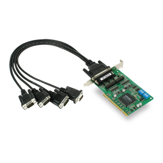
Industrial 4-Port RS-422/485 Serial Board for PCI Bus
This manual is also available on CD-ROM and at Moxa's Website
User's Manual
First Edition, January 2003
Moxa Technologies Co., Ltd.
Tel: +866-2-8919-1230
Fax: +886-2-8919-1231
www.moxa.com
support@moxa.com.tw
Advertisement
Table of Contents

Related Manuals for Moxa Technologies Industio CP134-UI


Summary of Contents for Moxa Technologies Industio CP134-UI
- Page 1 Industio Industio Industio CP-134U Series User’s Manual Industrial 4-Port RS-422/485 Serial Board for PCI Bus First Edition, January 2003 This manual is also available on CD-ROM and at Moxa’s Website Moxa Technologies Co., Ltd. Tel: +866-2-8919-1230 Fax: +886-2-8919-1231 www.moxa.com support@moxa.com.tw...
- Page 2 Information provided in this manual is intended to be accurate and reliable. However, Moxa Technologies assumes no responsibility for its use, or for any infringements on the rights of third parties that may result from its use.
- Page 3 MOXA Internet Services Customer satisfaction is our number one concern, and to ensure that customers receive the full benefit of our products, Moxa Internet Services has been set up to provide technical support, driver updates, product information, and user’s manual updates. The following services are provided E-mail for technical support .......
-
Page 4: Table Of Contents
Table of Contents Introduction................1-1 Overview .......................1-2 Features......................1-4 Package Checklist..................1-4 Hardware Installation ............2-1 CP-134U Series Block Diagrams ..............2-2 Installing the Industio CP-134U Series Board..........2-7 Software Installation.............. 3-1 Windows NT....................3-2 Windows 95/98 ....................3-10 Windows 2000/XP..................3-25 Linux......................3-37 Serial Programming Tools ............ 4-1 PComm Installation ..................4-2 PComm Programming Library.................4-2 RS-485 Programming ..................4-2... -
Page 5: Introduction
1 1 1 1 1 1 1 1 Introduction Welcome to the MOXA CP-134U Series of industrial 4-port RS-422/485 serial boards for the PCI bus. The following topics are covered in this chapter: ❑ Overview Features ❑ Package Checklist ❑... -
Page 6: Overview
Overview Industio—The Industrial Multiport Async Solution Moxa Industio Industio Industio Industio products are smart, multiport serial I/O solutions for industrial applications. The Industio Industio CP-134U Series boards, including CP134-UI and CP-134UL, are designed Industio Industio for a 32-bit PCI bus with the Plug and Play and Universal PCI feature. The ports for these boards can be configured independently, with ports 1 and 2 set to the RS-232, RS-422, or RS-485 interface, and ports 3 and 4 set to the RS-422 or RS-485 interface. -
Page 7: Universal Pci
Introduction PCI BIOS. This means that the board MUST be plugged into the computer first before installing the driver software. For more PCI information, refer to the Technical Reference Appendix. Universal PCI The 32/64-bit PCI local bus specification specifies both 3.3V and 5V connector types for the PCI hardware. -
Page 8: Features
Features The Industio CP-134U Series includes the following products: CP-134U 4 RS-422/485 ports, Universal PCI interface with embedded Surge Protection and Isolation Protection (16 KV ESD, 2 KV Isolation) CP-134UI 4 RS-422/485 ports, Universal PCI interface with embedded Surge Protection and Isolation Protection Below we list the outstanding features of the Industio CP-134U Series boards: Supports 4 independent serial ports—2 ports for RS-232 or RS-422/485, and 2 ports for RS-422/485... -
Page 9: Hardware Installation
2 2 2 2 2 2 2 2 Hardware Installation You will need to install both hardware and software for Industio CP-134U Series boards. The hardware installation procedure is given in this chapter, and the next chapter deals with software installation for various operating systems. The following topics are covered in this chapter: CP-134 Series Block Diagram ❑... -
Page 10: Cp-134U Series Block Diagrams
CP-134U Series Block Diagrams Industio CP-134U Series boards’ hardware configuration for IRQ number and I/O address is automatically assigned by the PCI BIOS. This means that the board MUST be plugged in first before installing the driver software. CP-134UI Industio CP-134U Series User’s Manual... - Page 11 Hardware Installation CP-134U The Industio CP-134U Series has two 30-pin jumpers and two sets of four DIP Switches on the board that allow the user to set the serial interface for each of the board’s four ports. Ports 1 and 2 can be set to RS-232, RS-422, RS-485 (2-wire), or RS-485 (4-wire). Ports 3 and 4 can be set to RS-422, RS-485 (2-wire), or RS-485 (4-wire).
-
Page 12: Jumper Settings
Jumper Settings The two on-board 30-pin jumpers are used to select between the RS-232 and RS-422/485 serial interfaces. If you select RS-422/485, then you will also need to set the DIP Switches to select between RS-422, RS-485 (4-wire), and RS-485 (2-wire). Note that the two ports can be configured independently. - Page 13 Hardware Installation Port 1 DIP Switch Settings S1-1 S2-1 RS-232 — — RS-422 — RS-485 (2-wire) RS-485 (4-wire) Port 2 DIP Switch Settings S1-2 S2-2 RS-232 — — RS-422 — RS-485 (2-wire) RS-485 (4-wire) Industio CP-134U Series User’s Manual 2-5...
- Page 14 Port 3 DIP Switch Settings S1-3 S2-3 RS-422 — RS-485 (2-wire) RS-485 (4-wire) Port 4 DIP Switch Settings S1-4 S2-4 RS-422 — RS-485 (2-wire) RS-485 (4-wire) Industio CP-134U Series User’s Manual...
- Page 15 Hardware Installation Installing the Indu Industio stio CP-134U Series Board Indu Indu stio stio Step 1: Power off the PC. Warning! To avoid damaging your system and board, make sure your computer is turned off before installing any board. Step 2: Remove the PC’s cover. Step 3: Remove the slot cover bracket if there is one.
-
Page 17: Software Installation
3 3 3 3 3 3 3 3 Software Installation In this chapter, the software driver installation, configuration, and driver update/removal procedures are described for various operating systems, including Windows NT, Windows 95/98, Windows 2000/XP, and Linux. Before proceeding with the software installation, complete the hardware installation, discussed in the previous chapter, “Hardware Installation.”... -
Page 18: Windows Nt
Windows NT Windows NT supports up to 256 serial ports, from COM1 to COM256. To fully integrate the advanced features of Windows NT, Moxa has developed multi-process and multi-thread, pure 32-bit Windows NT device drivers for the Industio CP-134U Series multiport boards. The driver conforms to the Win32 COMM API standard. -
Page 19: Installing The Driver
Software Installation Installing the Driver The following procedure is for installing the Industio CP-134U Series driver for the first time under Windows NT 4.0. Before taking these steps, make sure the board(s) have already been plugged into the system’s PCI slot(s). Log into NT as Administrator. - Page 20 5. Select “MOXA Smartio Smartio Smartio / Industio Smartio Industio Industio Family multiport board” from the “Select OEM Industio Option” dialog box, and then click [OK] to enter the “MOXA Smartio/Industio Configuration Panel” dialog box to start the installation. Click the [Add] button to open the Property dialog box to change port settings and advanced FIFO configurations done automatically by the system.
- Page 21 Software Installation The [Port #] window will open to allow you to change settings, as described below, for that particular port. Port Number You must set up all of the board’s ports with the desired “COM number,” which Industio CP-134U Series User’s Manual 3-5...
- Page 22 should not conflict with other COM numbers in use. In this “Individual Port Setting” dialog box, there are two ways to map physical ports to COM numbers, depending on whether you check the “Auto Enumerating COM Number” box. If “Auto Enumerating COM Number” is checked, and the COM number of the first port is specified, then subsequent ports are mapped to the next available COM number.
- Page 23 Software Installation 10. When you have finished the configuration, click on the [Close] button in the “Network Settings” dialog box. 11. Restart the Windows NT system. The new configuration will take effect when the system restarts. Note ! The latest configuration will not take effect unless the system restarts. 12.
- Page 24 Note ! Once the board and the driver are installed and the driver restarts successfully, you can start to develop applications with the PComm PComm library (see the PComm PComm “Serial Programming Tools” chapter) or the Microsoft Win32 API. You can also execute ready-made applications, such as PComm PComm utility Terminal emulator (see PComm...
- Page 25 Software Installation You may use this configuration panel to: Click on [Property] to enter the “Property” dialog box to configure the selected board with the correct “COM Number,” “Rx FIFO Trigger,” and “Tx FIFO Size.” See Steps 8 and 9 in the previous section, “Installing the Driver,” for more details. Click on [Add] to add one more board that has not yet been configured for the system.
-
Page 26: Windows 95/98
Removing the Driver To remove the driver for the Industio CP-134U Series board, Open the [Control Panel], click on the [Network] icon, and select the [Adapters] tab. 2. Select “MOXA Smartio Smartio / Industio Industio Family Adapter” from the adapter list, and then Smartio Smartio Industio... - Page 27 Software Installation Install the Smartio PCI board in the system. Start Windows 95/98 to detect the board. Driver installed before? Install the driver from the diskette. See the “First Time Driver Installation” section. Configure the port. See the “Port Configuration” section. The Industio CP-134U Series ports should now be ready for use.
- Page 28 First Time Driver Installation Stage This stage presents the steps for installing the Industio CP-134U Series board driver for the first time. The installation of the Industio CP-134U Series board for Windows 95 and Windows 98 are slightly different and will be described in two columns. Follow the steps in the left column for Windows 95, or the right column for Windows 98, respectively.
- Page 29 Software Installation Windows 95 Windows 98 Type A:\Windows.95 in the Location field, and 3. Select Other Devices and then click [Next] to then click [OK] in the [Select Other Location] continue. window. The system will start reading the files from the diskette. Click on [Finish].
- Page 30 Windows 95 Windows 98 Type E:\Software\Win98\Windows.95 and then click [OK]. The system will start reading the files from the diskette. Click on [Next] to continue. Click on [Next] to continue. 3-14 Industio CP-134U Series User’s Manual...
- Page 31 Software Installation Port Configuration Stage This stage presents the steps for configuring the Industio CP-134U Series board’s ports under Windows 95/98. After the driver is installed, the CP-134U Series Installation window will appear automatically, and the port mapping will be done automatically by the system. If one CP-134U Series board was already installed, and another CP-134U Series board is plugged in, then the system will prompt you to take care of port configuration, as discussed in this section.
- Page 32 defined Rx FIFO Trigger to all ports. Select a Tx FIFO Size from the Tx FIFO Size pull-down list. Tx FIFO sizes from 1 to 64 bytes are available, with the default value set at 64 bytes. Check the [Set the change to all ports] check-box if you want to apply the just defined Tx FIFO Size to all ports.
- Page 33 Software Installation Board and Port Ready Stage The Board and Port Ready Stages for Windows 95 and Windows 98 are slightly different. This last stage completes the driver installation. Windows 95 Windows 98 After configuring the ports, restart Windows 95 After configuring the ports, click the [Finish] before using the Industio CP-134U Series board’s button.
- Page 34 Configuring the Board and Ports Follow the procedure given below if you would like to reconfigure the COM numbers of ports for boards that are already installed under Windows 95/98. Since this is a PCI board, once the board is added or unplugged, the configuration will be automatically added or removed by the system.
- Page 35 Software Installation you would like to change. Click on the Port Setting button to open the Port x window. Note! Step 5 is optional if you want to assign COM numbers to the Port manually. Check the [Auto Enumerating COM Name] check-box to assign continuous COM numbers for subsequent ports.
- Page 36 Re-assign the Rx FIFO Trigger by selecting a number from the pull-down list. Check the [Set the change to all ports] check-box if you want to apply this setting to all ports. Rx FIFO trigger levels of from 1 to 62 bytes are available, with the default value set at 64 bytes.
- Page 37 Software Installation Once the CP-134U Series Port x [COMy] Properties window opens, click on the Port Settings tab. You may now make modifications to Bits per second, Data bits, Parity, Stop bits, or Flow control. Industio CP-134U Series User’s Manual 3-21...
- Page 38 Click OK to accept the changes. Updating the Driver This section will discuss how to update the Windows 95/98 driver to enhance the function of the board. Open the [Control Panel], click the [System] icon, and select the [Device Manager] tab.
- Page 39 Software Installation Click on the [Update Driver...] button. Click on the [Specify a location] checkbox and either type in the path to the file, or click on [Browse] to use Windows Explorer to locate the file, and then click on [Next] to continue.
- Page 40 Removing the Driver This section explains how to remove the Industio CP-134U Series board driver. Open the [Control Panel], double click on the [Add/Remove Programs] icon, and then select the [Install/Uninstall] tab. Click on the MOXA Smartio/Industio Driver option and then click on the [Add/Remove] button to start the driver removal.
-
Page 41: Windows 2000/Xp
Software Installation Windows 2000/XP Windows 2000/XP supports up to 256 serial ports, from COM1 to COM256. To fully utilize Windows 2000/XP’s multi-process and multi-thread advanced features, pure 32-bit Windows 2000/XP device drivers were developed for the Industio CP-134U Series and other MOXA multiport boards. - Page 42 3. Select Search for a suitable driver… and 3. Select Search for the best driver… and then then click on Next to continue. click on Next to continue. 4. Select Specify a location and then click on 4. Wait while the installation wizard searches. Next to continue.
- Page 43 Software Installation 5. Insert the Moxa Driver CD into the CD-ROM drive, and then specify the location of the file as F:/multi_bd/software/win2k as shown below (change the drive letter if needed). Click OK to continue. 5. Wait while the driver software is installed. 6.
- Page 44 7. The next window shows the model number of the board, and indicates that Windows has completed the driver installation. Click on Finish to continue with the rest of the installation procedure. 7. The next Found New Hardware Wizard window to appear indicates that Windows has identified the board’s serial ports, and is starting to install the ports.
- Page 45 Software Installation 8. Select Install the software from a specific location and then click on Next to continue. 9. Input the location of the driver in the text input 10. Select Search for a suitable driver for my box, or use the Browse button to locate the device [recommended], and then click on appropriate folder.
- Page 46 Next to continue. 10. Wait while the installation wizard searches. 12. Insert the Moxa Driver CD into the CD-ROM drive, and then specify the location of the file as F:/multi_bd/software/win2k as shown below (change the drive letter, if needed). Click OK to continue. 11.
- Page 47 Software Installation installation. 12. After all files have been copied to the system, the Completing the Found New Hardware Wizard window will open to indicate that it 14. After all files have been copied to the system, has finished installing “Port 0.” Click on the Completing the Found New Hardware Finish to install the board’s second port.
- Page 48 How to Check the Installation There are three ways to check the installation of the CP-134U Series board. Device Manager You can check the installation of the board by selecting Start Settings Control Panel System, and then click on the Device Manager button. Windows 2000 Windows XP 3-32...
-
Page 49: Event Log
Software Installation If the driver installation was successful, you will be able to see the model number of the CP-134U board listed under Multi-port serial adapters. You may also expand the Ports (COM & LPT) item to check the status of the COM ports. If you see a question mark on top of the icon, then the installation might have a problem. - Page 50 Removing the Driver You can uninstall the board by selecting Start Settings Control Panel System. Windows 2000 Windows XP 3-34 Industio CP-134U Series User’s Manual...
- Page 51 Software Installation Select the Hardware tab, and then click on Device Manager. Use the mouse to place the cursor over the CP-134U Series board under Multi-port serial adapters, and then click the right mouse button. Select the Uninstall… option. Windows 2000 Windows XP Click OK to proceed with the un-installation of the board.
- Page 52 The Device Manager window will automatically refresh to show that the driver and ports for the CP-134U Series board have been removed. 3-36 Industio CP-134U Series User’s Manual...
-
Page 53: Linux
Software Installation Linux NOTE: This section applies to Linux kernel 2.2.14 or later. The Moxa Smartio/Industio driver is included in the Linux kernel 2.2.14 or later versions. However, to use this built-in driver, you need some additional utilities that can be downloaded from the Moxa website, or software CD-ROM. -
Page 54: System Requirements
msdiag Diagnostic program for displaying installed Moxa Smartio/Industio boards. msmon Monitoring program to observe data count and line status signals. msterm A simple terminal program which is useful when testing serial ports. io-irq.exe Configuration program for setting up ISA boards. Please note that this program can only be executed under DOS. - Page 55 Software Installation installing the board. PCI IRQ Sharing Each port on the same multiport board will share the same IRQ. Up to 4 Moxa Smartio/Industio PCI Family multiport boards can be installed together on the same system, and it’s quite possible that they will all share the same IRQ. However, since the IRQ is assigned automatically by the system, the user does not need to worry about which IRQ is used for which board.
- Page 56 2nd board ttyM8 - ttyM15 cum8 - cum15 3rd board ttyM16 - ttyM23 cum16 - cum23 4th board ttyM24 - ttym31 cum24 - cum31 Board sequence This driver will activate ISA boards according to the parameter set in the driver. After all specified ISA boards have been activated, PCI board will be installed in the system automatically driven.
- Page 57 Software Installation the source code if you modify the source code. For example, if you change the driver's major number (see Section 3.7), then you will need to redo this step. Find "Makefile" in /moxa/mxser, and then run # make clean; make install The driver files "mxser.o"...
- Page 58 # mv mxser.c mxser.c.old For Red Hat 7.x users, you must create a link: # cd /usr/src # ln -s linux-2.4 linux Create link # cd /usr/src/linux/drivers/char # ln -s /moxa/mxser/driver/mxser.c mxser.c Configure the kernel: # cd /usr/src/linux # make menuconfig You will go into a menu-driven system.
- Page 59 Software Installation # make clean; make install Reboot Static driver configuration (for Linux kernel 2.0.3x, and 2.2.14 or earlier) Create link # cd /usr/src/linux/drivers/char # ln -s /moxa/mxser/driver/mxser.c mxser.c Modify tty_io.c # cd /usr/src/linux/drivers/char/ # vi tty_io.c Find pty_init(), insert "mxser_init()" as pty_init();...
- Page 60 If you use the 'lilo' utility, you should check the /etc/lilo.conf 'image' item specified in the 'vmlinuz' path, or you will load the wrong (or old) boot kernel image (vmlinuz). After checking /etc/lilo.conf, run "lilo". Note that if the result of "make bzImage" is ERROR, then you must go back to the Linux configuration setup.
-
Page 61: Verifying Driver Installation
Software Installation Insert the new major numbers into the driver’s source code. Run vi to open /moxa/mxser/driver/mxser.c. Locate the line that contains "MXSERMAJOR", and change the content as below: #define MXSERMAJOR #define MXSERCUMAJOR Run "make clean; make install" from /moxa/mxser/driver. Verifying driver installation You may refer to /var/log/messages to check the latest status log reported by this driver whenever it's activated. - Page 62 Setserial Supported Setserial parameters are listed as below. uart set UART type (16450-->disable FIFO, 16550A-->enable FIFO) close_delay set the amount of time(in 1/100 of a second) that DTR should be kept low while being closed. closing_wait set the amount of time (in 1/100 of a second) that the serial port should wait for data to be drained while being closed, before the receiver is disabled.
- Page 63 Software Installation equal to zero) for one Moxa board. Error msg: No interrupt vector can be set for the Moxa ISA board (CAP=xxx). Solution: Moxa ISA boards need an interrupt vector. Refer to the "Hardware Installation" chapter from the user's manual to set an interrupt vector. Error msg: Couldn't install the MOXA Smartio/Industio family driver! Solution:...
-
Page 65: Serial Programming Tools
4 4 4 4 4 4 4 4 Serial Programming Tools Moxa supports an easy to use yet powerful serial programming library and communication troubleshooting utilities under Windows NT, Windows 95/98, Windows 2000/XP, and DOS. You will save a lot of development time by using MOXA’s Serial Programming Tools. -
Page 66: Pcomm Installation
PComm Installation PComm PComm PComm To install PComm PComm, run \Setup.exe from the diskette. Note that the PComm PComm diagnostic and PComm PComm PComm PComm monitor utilities are for MOXA boards only. MOXA Windows NT, Windows 95/98, or Windows 2000/XP device drivers, as well as MOXA boards are required. The drivers are installed separately, with details given in the “Software Installation”... - Page 67 Serial Programming Tools How to transmit and receive data for Windows NT, and 95/98 In order to acquire precise timing control for RS-485 2-wire transmission, we recommend that you configure your Industio CP-134U Series ports as described below. There are 2 solutions to control RS-485 2-wire transmission. Solution 1 The following method is commonly used for RS-485 2-wire transmission: sio_SetWriteTimeouts(port, 0);...
-
Page 69: Connection Cables And Cable Wiring
5 5 5 5 5 5 5 5 Connection Cables and Cable Wiring Pinouts and Cable Wiring The CP-134U Series boards have one DB44 female port on the board that sends signals to four independent serial ports. The DB44 (Male) to 4 x DB9 (Male) cable (Model CBL-M44M9x4) or DB44 (Male) to 4 x DB25 (Male) (Model CBL-M44M25x4), both of which are available from Moxa, can be used to separate the signals coming from the board into the signals for the four different ports. - Page 70 RS-232 Interface When ports 1 and/or 2 are configured for the RS-232 interface, the pinouts are as shown below. CP-134U (RS-232) Port 1 Port 2 RS-422 Interface The RS-422 standard uses a balanced voltage digital interface to allow 10 Mbps communication over cables of up to 4000 feet in length.
- Page 71 Connection Cables and Cable Wiring RS-485 Interface The RS-485 standard is an enhanced version of the RS-422 balanced line standard. It allows multiple drivers and receivers to work on a multidrop network. A maximum of 32 drivers and 32 receivers can be set up on a multidrop network. The CP-134U Series supports both 2-wire half-duplex and 4-wire full-duplex RS-485 communications.
- Page 72 CP-134U (2-wire RS-485) Port 1 Port 2 Port 3 Port 4 13 Data+(B) Data+(B) Data+(B) Data+(B) 29 Data-(A) 25 Data-(A) 21 Data-(A) 17 Data-(A) Individual Port Pinouts In this subsection we give the pinouts for individual ports. Refer to the DB9 pinout diagrams if you are using the Model M44M9x4 cable, and refer to the DB25 pinout diagrams if you are using the Model M44M25x4 cable.
- Page 73 Connection Cables and Cable Wiring RS-422 DB25 Pin No. Signal Pin No. Signal TxD-(A) TxD+(B) TxD+(B) RxD+(B) RxD+(B) RTS+(B) RxD-(A) CTS+(B) RTS-(A) CTS-(A) RTS+(B) TxD-(A) CTS+(B) RxD-(A) CTS-(A) RTS-(A) RS-485 (4-wire) DB25 Pin No. Signal Pin No. Signal TxD-(A) TxD+(B) TxD+(B) RxD+(B) RxD+(B)
- Page 74 RS-485 (2-wire) DB25 Pin No. Signal Pin No. Signal Data-(A) Data+(B) Data+(B) Data-(A) Industio CP-134U Series User’s Manual...
- Page 75 Connection Cables and Cable Wiring Cable Wiring—DB9 RS-422 Point-to-point RS-422 Broadcasting CP-134U RS-422 Device CP-134U RS-422 Device 1 TxD+(B) RxD+(B) TxD+(B) RxD+(B) TxD-(A) RxD-(A) RxD+(B) TxD+(B) RxD+(B) TxD+(B) TxD-(A) RxD-(A) RxD-(A) TxD-(A) RxD-(A) TxD-(A) RS-422 Device N RxD+(B) TxD+(B) RxD-(A) TxD-(A) CP-134U –...
- Page 76 Multidrop 2-wire RS-485 (half-duplex) CP-134U RS-485 Device 1 Master Slave Data+ Data+ Data- Data- RS-485 Device N Slave Data+ Data- Multidrop 4-wire RS-485 (full-duplex) CP-134U RS-485 Device 1 Master Slave TxD+(B) RxD+(B) TxD-(A) RxD-(A) RxD+(B) TxD+(B) RxD-(A) TxD-(A) RS-485 Device N Slave RxD+(B) RxD-(A)
-
Page 77: Impedance Matching And Termination Resistors
Connection Cables and Cable Wiring Impedance Matching and Termination Resistors When using RS-422/485 serial communications, an electrical signal that travels through two different resistance junctions in a transmission line will sometimes give rise to signal reflection due to the impedance mismatch. Signal reflection causes signal distortion, which in turn contributes to communication errors. -
Page 79: Troubleshooting
6 6 6 6 6 6 6 6 Troubleshooting Common Industio CP-134U Series problems and possible solutions are listed below. If you still have problems, contact your dealer or Moxa for help, or use the Problem Report Form at the end of this manual to report problems to your dealer. General Troubleshooting The MOXA PCI board cannot be detected by the MOXA driver while installing the driver. - Page 80 The MOXA board and driver are activated but cannot transfer (transmit/receive) data. Hardware Causes and Solutions: a. Make sure the cable wiring is connected correctly. Refer to the “Connection Cable and Cable Wiring” chapter for correct cable connections. b. The cable or the board are probably defective. Try other ports, cables, or boards to verify this, or use the PComm PComm Diagnostic utility to test the MOXA board’s and port PComm...
-
Page 81: Windows Nt
Troubleshooting Windows NT This section is specific for troubleshooting under Windows NT. For general problems and solutions, see the previous section, “General Troubleshooting.” After the system reboots, the error message “Another driver in the system, which did not report its resources, has already claimed the interrupt used by xxx.” appears in the Event Log. -
Page 82: Windows 95/98
Windows 95/98 This section is specific for troubleshooting under Windows 95/98. For general problems and solutions, see the previous section, “General Troubleshooting.” The system fails to find the Industio Industio Industio CP-134U Series board! Industio The board(s) is(are) not plugged properly. The slot the boards are plugged into is defective. -
Page 83: Specifications
A A A A A A A A Technical Referen Technical Reference Technical Referen Technical Referen Specifications Bus interface 32-bit PCI Number of ports Max. No. of boards I/O address Assigned by PCI BIOS Assigned by PCI BIOS Comm. controller 16C550C or compatible Transmission speed 50 bps –... -
Page 84: Pci
Power requirement CP-134U 420 mA max. (+5V) CP-134UI 700 mA max. (+5V) CP-134IS 710 mA max. (+5V) Dimensions CP-134U 120 × 80 mm (W × D) CP-134UI 120 × 110 mm (W × D) CP-134S 120 × 80 mm (W × D) CP-134IS 120 ×... - Page 85 Industio CP-134U Series User’s Manual A-1...
Need help?
Do you have a question about the Industio CP134-UI and is the answer not in the manual?
Questions and answers