Table of Contents
Advertisement
Quick Links
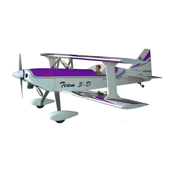
0.91 cu.in. displacement 4-stroke
Radio required : 4 channels, 5 servos airplane radio
Wing Span
Wing Area
Flying Weight
Fuselage Length
Warning !This model is not a toy.
It is designed for maximum performance. Please seek advice if one is not familiar with this kind
of engine powered precision model. Operating this model without prior preparation may cause
injuries. Remember, safety is the most important thing. Always keep this instruction manual at
hand for quick reference.
Specifications
* Specifications are subject to change without notice.*
INSTRUCTION MANUAL
- 90
- 90
49 in / 1240mm
818sq in / 52.8 sq dm
8.1 lbs / 3700 g
52.5 in / 1330 mm
ALMOST-READY-TO-FLY (ARF) SERIES
FACTORY PRE-FABRICATED
MADE IN CHINA
Advertisement
Table of Contents

Related Manuals for TWM Ultimate-90


Summary of Contents for TWM Ultimate-90
- Page 1 INSTRUCTION MANUAL - 90 - 90 0.91 cu.in. displacement 4-stroke Radio required : 4 channels, 5 servos airplane radio Specifications Wing Span 49 in / 1240mm Wing Area 818sq in / 52.8 sq dm Flying Weight 8.1 lbs / 3700 g Fuselage Length 52.5 in / 1330 mm * Specifications are subject to change without notice.*...
-
Page 2: Parts List
Parts List ANTI-VIBRATION MOUNT PL5214094 -- 1 set 1.MAIN WING(Lower) -- 1 pc . INCLUDE:SOCKET HEAD SCREW M4x35mm -- 4 pcs 2.SCREW PM2x20mm -- 6 pcs S CREW K M3x20mm -- 8 p cs STRAPER -- 2 pcs W ASHER d 4xD12mm -- 8 p cs CLEVIS -- 2 pcs M 3 N YLON I NSERT L OCK U T --8 pc s FUEL TUBE 6x5mm -- 4 pcs... -
Page 3: Before You Begin
- 90 - 90 I N D E X BEFORE YOU BEGIN P. 1 PARTS LIST P. 2 ASSEMBLY P. 3 - 11 SAFETY PRECAUTIONS P. 11 BEFORE YOU BEGIN Read through the manual before you begin, so you will have an overall idea of what to do. Check all parts. -
Page 4: Aileron Servo
Main Wing (Lower) Aileron Servo Lead CABANE MOUNT Pre-glued Aileron Servo (Lower) Screw PM2x20mm Ø1mm pilot holes for World Models Straper tri-horn are pre-drilled. Please look for pin-hole marks at under side of Wood Block control surfaces. 9x10x21mm Fuel Tube Ø6x5mm PM2x20mm Clevis... -
Page 5: Stabilizer & Elevator
Main Wing (Upper) CABANE MOUNT Pre-glued Bottom View PWA3x12mm Stabilizer & Elevator 98mm Screw PWA3 x 12mm 42mm Stabilizer Tube Pre-glued D9.6x250mm A=A' Bottom View Wire Ø3x141mm M3 x 6mm Set Screw M3 x 6mm Set Screw PWA3 x 12mm M3 x 6mm Set Screw M3 x 6mm Set Screw Bottom View... -
Page 6: Tail Landing Gear
Tail Landing Gear 2.5mm 1.5mm Screw PA3x12mm Collar 2.6mm 2.6mm Collar PA3x12mm M3x3mm Set Screw Bottom View Rudder Pullwire Fuel Tube 6 x 5mm Press down the center 1/3 portion Wire Ø1x534mm Wire Screw PM2x20mm Ring Clevis Copper Tube Rigging Coupler Ø1mm pilot holes for World Models tri-horn 1.8 x 27mm are pre-drilled. -
Page 7: Main Landing Gear
Main Landing Gear Washer Screw PM5x50 mm d5xD12mm d4xD9mm PM4x16mm Collar 5.1mm Washer Screw PM4x16mm M3x18mm NYLON BOLT Washer d4xD9mm Bottom View Completed Engine Mount Screw Engine Mount PM4x30mm PL5111080 Washer d4xD12mm Apply thread locker to screws. PM4x30mm d4xD12mm Blind nuts are off-centered to keep Washer the spinner at the fuselage axis. - Page 8 Servo Set LINKAGE CONNECTOR Set Screw 3x3mm Included with the radio Set. Linkage Connector Washer Throttle Servo. Please refer to attached sheet for linkage connector installation. Engine SOCKET HEAD SCREW M4x35mm M4 NYLON INSERT LOCK NUT d4xD12mm Washer NYLON INSERT LOCK NUT Washer d4xD12mm d4xD12mm...
-
Page 9: Radio Equipment
Radio Equipment Install and arrange the servo as shown in the diagram. Elevator Servo PLYWOOD BALSA Front Press down the center BALSA 5x61x126mm Fuel Tube 6x6x61mm 1/3 portion 6x6x61mm Ø6x5mm Sponge Wire Elevator Servo Copper Tube Elevator Pushrod Ø1.8x70mm Straper Straper M2 Nut PLYWOOD... - Page 10 Main Wing (Lower) PM4x40mm Washer d4xD15mm Screw PM4x40mm Screw PM4x30mm Washer d4xD15mm PM4x30mm Washer Bottom View d4xD15mm Main Wing Pierce the two pre-drill Screw Plywood PM3x20mm PM3x16mm holes at upper wing center 6x20x36.6mm cabane mount and fasten the center cabanes with Screw PM3x20mm PM3x16mm &...
- Page 11 Main Wing Ø1mm pilot holes for World Models horn are pre-drilled. Please Screw PM2x10mm look for pin-hole marks at under side of control surfaces. Horn Clevis Pushrod M2xD4x212mm Fuel Tube Ø6x5mm Clevis PM2x10mm Horn Wing Setting Adjust the wing and fuselage configuration as in the diagrams.
- Page 12 Adjust the control throws as shown in the diagram. These throws are good for general flying. You can adjust according to your personal preference. Elevator 50mm 50mm Rudder 80mm 80mm Ailerons 15mm 15mm The ideal C.G. position is 120mm (4.72 in.) behind the leading edge measured at top wing center line.
Need help?
Do you have a question about the Ultimate-90 and is the answer not in the manual?
Questions and answers