Table of Contents
Advertisement
Quick Links
Requires:
Wing Span
Wing Area
Flying Weight
Fuselage Length
Warning! This model is not a toy.
It is designed for maximum performance. Please seek advice if one is not familiar with this kind
of engine powered precision model. Operating this model without prior preparation may cause
injuries. Remember, safety is the most important thing. Always keep this instruction manual at
hand for quick reference.
The World Models
Manufacturing Co., Ltd.
www.theworldmodels.com
A341PO31811702
5-channel radio w/ 5 standard servos,
2-stroke 0.40-0.46 engine
4-stroke 0.70-0.81 engine
Specifications
*Specifications are subject to change without notice.*
56.5 in / 1435 mm
558 sq in / 36 sq dm
6.8 Ib / 3100 g
51 in / 1290 mm
ALMOST-READY-TO-FLY(ARF)SERIES
INSTRUCTION MANUAL
( A341 )
FACTORY PRE-FABRICATED
MADE IN CHINA
Advertisement
Table of Contents

Related Manuals for TWM P-51D Strega-40


Summary of Contents for TWM P-51D Strega-40
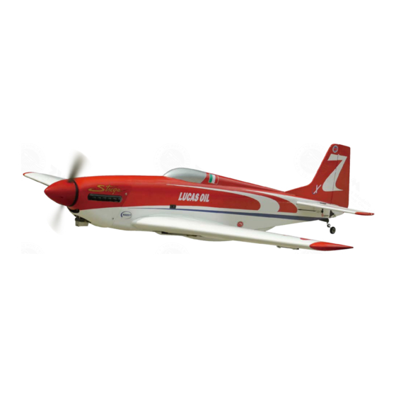
- Page 1 INSTRUCTION MANUAL ( A341 ) Requires: 5-channel radio w/ 5 standard servos, 2-stroke 0.40-0.46 engine 4-stroke 0.70-0.81 engine Specifications Wing Span 56.5 in / 1435 mm Wing Area 558 sq in / 36 sq dm Flying Weight 6.8 Ib / 3100 g Fuselage Length 51 in / 1290 mm *Specifications are subject to change without notice.*...
-
Page 2: Before You Begin
INDEX BEFORE YOU BEGIN PARTS LIST ASSEMBLY P.3-P.13 SAFETY PRECAUTIONS P.14 BEFORE YOU BEGIN Read through the manual before you begin, so you will have an overall idea of what to do. Check all parts. If you find any defective or missing parts contact your local dealer. Please DRY FIT and check for defects for all parts that will require CA or Epoxy for final assembly. -
Page 3: Parts List
Parts List 1. MAIN WING -- 1 pair 10. FUEL TANK 450cc -- 1 set 2. PUSHROD Ø1.8x95mm w/ Threads (For Aileron) -- 2 pcs CABLE TIE 1.5x5x400mm -- 1 pc. TRI-HORN PL4111221 -- 2 sets DOUBLE-SIDE TAPE 40x100mm -- 1 pc. SCREW PB2x18mm -- 4 pcs 11. - Page 4 Main Wing Electric retract wire Bottom View Apply instant type CA glue to both sides of each hinge. Aileron Pushrod & Retractable Landing Gear 4.8V - 6.0V operation Screw PB2x18mm only, higher voltage will burn out the PWA2.3x8mm retract motor. Screw PB2x14mm Screw...
-
Page 5: Stabilizer & Elevator
Stabilizer & Elevator (Stabi l i zer) (Mai n Wi ng) B=B' Temporary install the main wing, adjust leveling of the stabilizer to make it as parallel to the main wing as possible Apply instant type CA glue to both sides of each hinge. Vertical Fin &... -
Page 6: Elevator Pushrod
Elevator Pushrod Screw PB2x14mm Screw PB2x12mm PB2x14mm Fuel Tube D6x5mm PB2x12mm Tri-horn M3 x 14mm Pushrod Ø1.8x500mm Clevis Bottom View Ø1mm pilot holes for World Models horn are pre-drilled. Please look for pin-hole marks at under side of control surfaces. Rudder Pushrod Screw PB2x12mm... -
Page 7: Engine Mount
Engine Mount M4x25mm Socket Head Screw Washer Engine Mount PL5111050 d4xD9mm d4xD9mm Blind nuts are off-centered M4x25mm to keep the spinner at the fuselage axis. Apply thread locker to screws For short engines, add base brackets. Engine Screw PM3.5x30mm Washer d3.5xD8mm Nu t M3.5... -
Page 8: Fuel Tank
Fuel Tank Front Double-sided Tape 40x100mm Cable Tie 1.5x5x400mm Cowling Screw PWA2.6x12mm d1.5xD6.5mm Silicon Grommets Cowling d1.5xD6.5mm Grommet Spinner PWA2.6x12mm Silicon Grommets PWA2.6x12mm Fuselage First insert the grommet to the cowling then apply screw. A341PO31811702... - Page 9 Servo Set Set Screw 3x3mm Linkage Connector 3x3mm Set Screw Throttle Pushwire Washer Washer Washer 1.5mm Throttle Servo M2 Nut Please refer to the attached sheet for linkage connector installation. Servos Setting Install and arrange the servo as shown in the diagram. J1(Pushrod Ø1.8x75mm) Throttle Servo Sponge...
- Page 10 Main wing Screw HM4x30mm Screw HM4x55mm Washer d4xD15mm HM4x30mm HM4x55mm d4xD15 Washer d4xD15 Washer Air Scoopy Screw PM3x13mm Washer d3xD7mm PM3x13mm d3xD7 Washer Air Scoopy Completed A341PO31811702...
- Page 11 Wing Setting & Decals A=A` B=B` C=C` A341PO31811702 P.10...
-
Page 12: Control Throws
Control Throws Adjust the control throws as shown in the diagram. These throws are good for general flying. You can adjust according to your personal preference. Elevator 15mm 15mm Rudder 28mm 28mm Ailerons C.G. The ideal C.G. position is 128mm (5.04 in.) behind the leading edge measured at where the wing meets the fuselage. - Page 13 Warning! I m portant S afety P recauti ons F irst tim e flyer sh o u ld n ever fly b y h im self / h erself. Assistan ce fro m exp erien ced flyer is ab so lu tely n ecessary. Pre - flig h t ad ju stm en t m u st b e d o n e b efo re flyin g , it is very d an g ero u s to fly a b ad ly p re - ad ju sted aircraft.
- Page 14 LINKAGE CONNECTOR HW7111050 & HW7111060 Drill 2mm hole at servo horn. Insert linkage connector into servo horn. Make sure shoulder of screw is cleared from servo horn. Add washer to reduce play if necessary. Shoulder Tighten up the round nut against the shoulder.
- Page 15 Usage of the transparent 3D template This transparent 3D template is used for position guidance of the actual cutting of the pre-painted cowling. Simply cut the transparent 3D template to fit your engine and exhaust pipe, then slide onto the actual cowling and use as template to mark the openings required for final cutting.
- Page 16 A341PO31811702...
Need help?
Do you have a question about the P-51D Strega-40 and is the answer not in the manual?
Questions and answers