Table of Contents
Advertisement
Quick Links
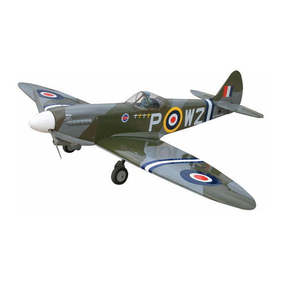
SPITFIRE G.S.
ARF
1.60 cubic inch displacement 2-stroke(glow)
Requires: 6 channel
2 low profile retract servos
Wing Span
Wing Area
Flying Weight
Fuselage Length
Warning! This model is not a toy.
It is designed for maximum performance. Please seek advice if one is not familiar with this kind of
engine powered precision model. Operating this model without prior preparation may cause injuries.
Remember, safety is the most important thing. Always keep this instruction manual at hand for quick
reference.
-
radio w/ 7 standard servos and
Specifications
* Specifications are subject to change without notice.*
INSTRUCTION MANUAL
80 in / 2030 mm
1138 sq in / 73.4 sq dm
13 lb / 5850 g
68 in / 1730 mm
ALMOST-READY-TO-FLY (ARF) SERIES
FACTORY PRE-FABRICATED
MADE IN CHINA
Advertisement
Table of Contents

Related Manuals for TWM SPITFIRE G.S


Summary of Contents for TWM SPITFIRE G.S
-
Page 1: Specifications
INSTRUCTION MANUAL SPITFIRE G.S. 1.60 cubic inch displacement 2-stroke(glow) Requires: 6 channel radio w/ 7 standard servos and 2 low profile retract servos Specifications Wing Span 80 in / 2030 mm Wing Area 1138 sq in / 73.4 sq dm... -
Page 2: Before You Begin
SPITFIRE G.S. I N D E X BEFORE YOU BEGIN P. 1 PARTS LIST P. 2 ASSEMBLY P. 3 - 12 SAFETY PRECAUTIONS P. 12 BEFORE YOU BEGIN Read through the manual before you begin, so you will have an overall idea of what to do. - Page 3 Parts List 1.MAIN WING -- 1 pair 2.RETRACTABLE LANDING GEAR -- 1 set RETRACTABLE LANDING GEAR COVER -- 1 set 9.ENGINE MOUNT PL511120 -- 1 set PUSHROD Ø1.8x45mm(For Retractable) -- 2 pcs SCREW M6x30mm -- 4 pcs MAIN WHEEL Ø103mm -- 2 pcs WASHER d6xD15mm -- 4 pcs COLLAR Ø5.7mm w/set screw -- 4 sets BLIND NUT M6xD18mm -- 4 pcs...
- Page 4 Flap & Aileron Apply instant type CA glue to both sides of each hinge. Pre-glued Aileron Servo lead Bottom View Landing gear & Retract Servos Screw PM2x8mm PM2x8mm M2 NUT Screw PWA 2.3 8mm d2xD5mm Washer d2xD5 Washer PWA 2 .3x8mm Bottom View Retract Servos Covering Film...
- Page 5 Flap & Aileron Servos Screw PM2x14mm Fuel Tube Straper Ø6x5mm Screw PM2x25mm Screw PWA 2x12 mm 1.5mm PWA2x12mm PM2x25mm Clevis Fuel Tube Ø6x5mm Tri-horn M3x14mm( PM2x14mm Clevis Fuel Tube Ø6x5mm Push Rod 1.8x100mm Ø Push Rod 1.8x110mm Ø Tri-horn M3x14mm( Æ...
-
Page 6: Stabilizer & Elevator
Stabilizer & Elevator Screw PA3x12mm Washer PA3x12mm d3xD7mm 97mm 60mm Stabilizer Tube A=A' D9.5x256mm d3xD7mm Pre-glued PA3x12mm d3xD7mm Completed Vertical Fin & Rudder pre-glued A=A' Completed... -
Page 7: Tail Landing Gear
S e t S c r e w 3 x 3 m m Plastic Collar Adjust clearance of linkage by adding or removing washer TWM PL8210010 CLEVIS WRENCH PWA 2 x 12mm PWA 2 x 12mm Elevator Linkage Fuel Tube Ø6x5mm... -
Page 8: Rudder Pullwire
Rudder Pullwire Fuel Tube Ø 6x5mm Screw PM 2x30mm Ring Clevis » 38mm Rigging Coupler 163mm » Ø1.8x27mm Copper Tube PM2x30mm M 2 N u t Ø1mm pilot holes for World Models tri-horn are pre-drilled. Please look for pin-hole marks at side of control surfaces. -
Page 9: Fuel Tank
Fuel Tank Install Plywood 3x41x125mm (For fixing fuel tank) Fuel Tank 800cc Plywood 3x41x125mm Fuel Tank Balsa 800cc 8x8x41mm Bottom View Engine M4 Nylon Insert Lock Nut M 4 x 3 5 m m S c r e w d4xD12mm KM3x20mm Washer M4 Nylon Insert Lock Nut Nylon Insert Lock Nut... - Page 10 3x3mm Set Screw Servo Set Included with the radio Set. LINKAGE CONNECTOR Set Screw 3x3mm Linkage Connector Washer Washer 2m m Throttle Servo. Washer Please refer to attached sheet for linkage connector installation. Press down the center Copper Tube Servos 1/3 portion Balsa 8x8x41mm...
- Page 11 Cowling First insert the grommet to the cowling then apply screw. Screw PWA2.6 x 12 mm d1.5 x D6.5 mm d1.5 x D6.5 mm Silicon Grommet Silicon Grommet Quick Release Nylon Rivet Screw KA 2.3 x 8 mm PWA2.6 x 12 mm Quick Release Nylon Rivet 4 mm KA 2.3 x 8 mm...
- Page 12 Canopy Screw PWA2.3x8 mm d1.5 x D6.5 mm Silicon Grommet Apply double-sided tape Pilot First insert the grommet to the canopy then apply screw. Silicon Grommet PWA2.3 x 8 mm d1.5xD6.5mm Wing Setting Adjust the wing and fuselage configuration as show in the diagrams. A = A ' B = B ' C = C '...
- Page 13 Pre - flight adjustment must be done before flying, it is very dangerous to fly a badly pre - adjusted aircraft. 1.60 2 SPITFIRE G.S. is specially designed to be powered by stroke glow engine, using a more powerful engine does not mean better performance. In fact, over powered engine may cause severe damage and injuries.
-
Page 14: Landing Gear
ADDENDUM LINKAGE CONNECTOR HW7111030 & HW7111060 Drill 2mm hole at servo horn. Insert linkage connector into servo horn. Make sure shoulder of screw is cleared from servo horn. Add washer to reduce play if necessary. Shoulder Tighten up the round nut against the shoulder. - Page 15 Should you require to bend the anding gear wire, please insert a round metal bar into the spring coil and apply force there as leverage. Bending the wire directly may damage the mounting block structure. Round metal bar P.14...
- Page 16 ANTI-VIBRATION MOUNT INSTALLATION For Engine Mount (PL5911120) Counter Sink 3.2mm 5.1mm 4.1mm edges are Make sure the rounded f a c ing t he s hoc k a bs or bing SILICON PAD. 3.2mm 1.----- KM3x20mm Screw 2.----- Copper Tube 3.----- M3 Nylon Insert Lock Nut 4.----- M4 Nylon Insert Lock Nut 5----- 4mm Washer...
Need help?
Do you have a question about the SPITFIRE G.S and is the answer not in the manual?
Questions and answers