Table of Contents
Advertisement
Quick Links
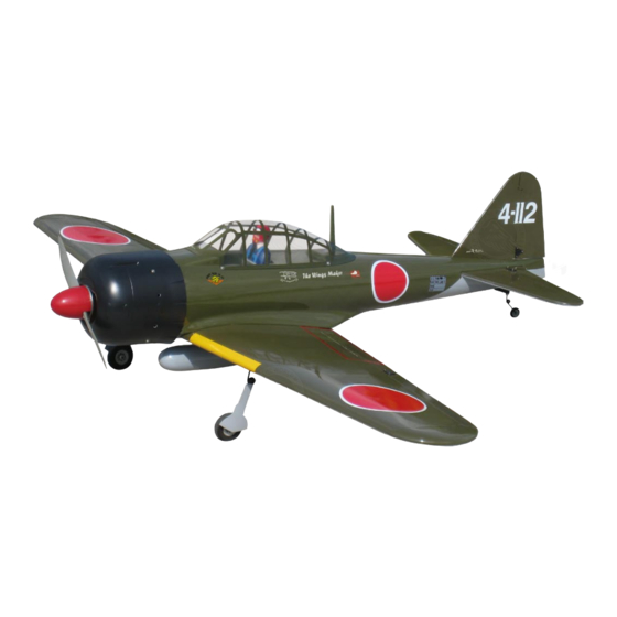
Zero Fighter 60S
0.60-0.75 cu. in. displacement 2-stroke
Requires : 6-channel radio w/ 6 standard servos
Wing Span
Wing Area
Flying Weight
Fuselage Length
Wa rning ! This m ode l is not a toy.
It is designed for maximum performance. Please seek advice if one is not familiar with this kind
of engine powered precision model. Operating this model without prior preparation may cause
injuries. Remember, safety is the most important thing. Always keep this instruction manual
at hand for quick reference.
The World Models
Manufacturing Co., LTD.
www.theworldmodels.com
A064SPO29991407
and 1 low profile retract servo
Specifications
* Specifications are subject to change without notice.*
60.0 in / 1520 mm
635 sq in / 41.0 sq dm
7.5 lbs / 3400 g
45.5 in / 1150 mm
FACTORY PRE-FABRICATED
ALMOST-READY-TO-FLY (ARF) SERIES
INSTRUCTION MANUAL
(A064S)
MADE IN CHINA
Advertisement
Table of Contents

Related Manuals for TWM Zero Fighter 60S


Summary of Contents for TWM Zero Fighter 60S
- Page 1 INSTRUCTION MANUAL Zero Fighter 60S (A064S) 0.60-0.75 cu. in. displacement 2-stroke Requires : 6-channel radio w/ 6 standard servos and 1 low profile retract servo Specifications Wing Span 60.0 in / 1520 mm Wing Area 635 sq in / 41.0 sq dm Flying Weight 7.5 lbs / 3400 g...
-
Page 2: Before You Begin
I N D E X BEFORE YOU BEGIN P. 1 P. 2 PARTS LIST P.3-10 ASSEMBLY SAFETY PRECAUTIONS P.11 BEFORE YOU BEGIN Read through the manual before you begin, so you will have an overall idea of what to do. Check all parts. -
Page 3: Parts List
Parts List M4 NUT -- 8 pcs 1. MAIN WING -- 1 pair THROTTLE PUSHWIRE Ø1.2x300mm -- 1 pc. PLASTIC TUBE d2XD3x200mm -- 1 pc. 2. RETRACTABLE LANDING GEAR -- 1 set SCREW KA3x14mm -- 8 pcs 14. COWLING --1 pc. RIGHT ANGLE WHEEL SPACER PL4121040 -- 2 sets TRANSPARENT 3D TEMPLATE -- 1 pc. -
Page 4: Aileron Servo
Main Wing Peel off shaded portion covering film Aileron Servo Lead Pre-glued Bottom View 3mm Set Screw Retractable Langing Gear Set Screw KA3x14mm Collar 4.1mm Screw KA3x14mm Bottom View PWA2x8mm Aileron Servo Screw PWA2 x 8mm Bottom View A064SPO29991407... - Page 5 Ø Screw Tri-Horn Fuel Tube PB2x16mm M3x14mm Ø6x5mm Pushrod Ø1.8x90mm TWM PL8210010 Bottom View CLEVIS WRENCH Main Wing Please apply glue to all surfaces of wing Joiner. Peel off shaded portion covering film for lead to another aileron servo Peel off shaded portion covering film.
- Page 6 Flap Servo Plywood 2x8x20mm Peel off shaded portion covering film. 1.5mm Straper TWM PL8210010 Fuel Tube CLEVIS WRENCH 6x5mm Clevis Ring Drop Tank Setup Drop Tank Socket Head Screw Washer Washer Main Wing Washer Completed Bottom View A064SPO29991407...
-
Page 7: Fuel Tank
Stabilizer/ Elevator A = A' (Stabilizer) (Main Wing) B=B' Temporary install the main wing,adjust leveling of the stabilizer to make it as parallel to the main wing as possible. Pre-glued Pre-glued Vertical Fin / Rudder Pre-glued Screw Pre-glued PA3x12mm Set Screw Collar 2.1mm 3mm Set Screw... - Page 8 Engine Mount Socket Head Screw M4x25mm Engine Mount PL5111070 Washer d4xD9mm Washer d4xD9mm Blind nuts are off-centered to keep the spinner at the fuselage axis. M4x25mm Install Engine position Engine Spinner 62mm Socket Head Screw M4x30mm Fire Wall Washer Plastic Tube d4xD9mm d2xD3x200mm 115mm...
-
Page 9: Rudder Pushrod
D6.5mm Ø1mm pilot holes for The World Models tri-horn are pre-drilled. Rudder Pushrod Please look for pin-hole marks at side of control surfaces. Screw PB2x12mm TWM PL8210010 CLEVIS WRENCH Peel off shaded portion covering film. Tri-horn Clevis M3 x 14mm Fuel Tube Ø6x5mm... -
Page 10: Radio Equipment
Servo Set 3x 3mm Set Screw 3x3mm Set Screw Throttle Pushwire Linkage Connector Washer M2 Nut Washer 1.5mm 2mm Washer Throttle Servo M2 Nut Please refer to the attached sheet for linkage connector installation. Radio Equipment Fix the throttle servo tray either to the right or left side of the fuselage according to your throttle pushrod Included with the... - Page 11 Main Wing M4x35mm Socket Head Screw M4x35mm d4x15mm Washer d4x15mm Wing Setting Adjust the wing and fuselage configuration as shown in the diagrams. A = A' B = B' C = C' Control Trows Adjust the control throws as shown in the diagram.
-
Page 12: Important Safety Precautions
# First time flyer should never fly by himself / herself. Assistance from experienced flyer is absolutely necessary. # Pre-flight adjustment must be done before flying, it is very dangerous to fly a badly pre-adjusted aircraft. ZERO FIGHTER 60S is specially designed to be powered by 50 c.c. gasoline engine, using a more powerful engine does not mean better performance. - Page 13 LINKAGE CONNECTOR HW7111050 & HW7111060 Drill 2mm hole at servo horn. Insert linkage connector into servo horn. Make sure shoulder of screw is cleared from servo horn. Add washer to reduce play if necessary. Shoulder Tighten up the round nut against the shoulder.
- Page 14 Usage of the transparent 3D template This transparent 3D template is used for position guidance of the actual cutting of the pre-painted cowling. Simply cut the transparent 3D template to fit your engine and exhaust pipe, then slide onto the actual cowling and use as template to mark the openings required for final cutting.
-
Page 15: Optional Parts
Optional Parts ACCESSORIES) 180mm Extension Fuel Filler Code No. Size Package Code No. Size Package KW0011800 PL8110030 180mm 1 set 15 x 22 x 49mm 1 x 1 pc 180mm Y-Cord Code No. Size Package KW0021800 180mm 1 pc Clevis Wrench Code No. - Page 16 A064SPO29991407...
Need help?
Do you have a question about the Zero Fighter 60S and is the answer not in the manual?
Questions and answers