Table of Contents
Advertisement
Quick Links
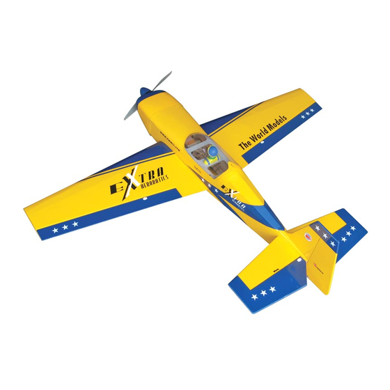
Extra 300 EP ( 40 )
Requires : 4-channel radio w/ 4 mini servos,
Wing Span
Wing Area
Flying Weight
Fuselage Length
Warning ! This model is not a toy.
It is designed for maximum performance. Please seek advice if one is not familiar with this kind
of electric powered precision model. Operating this model without prior preparation may cause
injuries. Remember, safety is the most important thing. Always keep this instruction manual at
hand for quick reference.
The World Models
Manufacturing Co., Ltd.
www.theworldmodels.com
E271XMPO26801110
450W Motor System
Outrunner Motor KM374810,
w/ Propeller Adaptor HW2340102, 40A
Brushless ESC with 11x8E proepller, 4 cells
14.8V 3200mAh Li - Po battery & charger.
*Specifications are subject to change without notice.*
Specifications
50.5 in / 1280 mm
450 sq in / 29 sq dm
53.5 oz / 1510 g
42.5 in / 1100 mm
INSTRUCTION MANUAL
FACTORY PRE-FABRICATED
ALMOST-READY-TO-FLY(ARF)SERIES
MADE IN CHINA
Advertisement
Table of Contents

Related Manuals for TWM Extra 300 EP (40)


Summary of Contents for TWM Extra 300 EP (40)
- Page 1 INSTRUCTION MANUAL Extra 300 EP ( 40 ) 450W Motor System Requires : 4-channel radio w/ 4 mini servos, Outrunner Motor KM374810, w/ Propeller Adaptor HW2340102, 40A Brushless ESC with 11x8E proepller, 4 cells 14.8V 3200mAh Li - Po battery & charger. Specifications Wing Span 50.5 in / 1280 mm...
-
Page 2: Before You Begin
Extra 300 EP ( 40 ) INDEX BEFORE YOU BEGIN PARTS LIST ASSEMBLY P.3-P10 SAFETY PRECAUTIONS P.10 BEFORE YOU BEGIN Read through the manual before you begin, so that you can have an overall idea of what to do. Check all parts. If you find any defective or missing parts contact your local dealer. Please DRY FIT and check for defects for all parts that will require CA or Epoxy for final assembly. -
Page 3: Parts List
Parts List 1. MAIN WING -- 1 pair 9. MAIN LANDING GEAR -- 1 pc. MAIN WHEEL Ø40mm -- 2 pcs 2. SCREW PB2x16mm -- 4 pcs COPPER TUBE d3.1xD4x5mm -- 2 pcs CLEVIS PL4112105 -- 2 pcs SCREW PWA2x6mm -- 4 pcs STRAPER PL4112106 -- 2 pcs SCREW PA2.6x10mm -- 3 pcs FUEL TUBE d2xD4x4mm -- 4 pcs... -
Page 4: Aileron Servo
Bottom View Aileron Servo Ø1mm pilot holes for World Models horn are pre-drilled. Please PB2x16mm Screw look for pin-hole marks at under side of control surfaces. TWM PL8210010 CLEVIS WRENCH Straper Fuel Tube d2xD4x4mm PB2 x 16mm Clevis... -
Page 5: Tail Landing Gear
Vertical Fin & Rudder Apply instant type CA glue to both sides of each hinge. Completed Tail Landing Gear PA2.6x12mm Screw PA2.6x12mm PA2.6x12mm PM2x10mm Screw 1.5mm 2.1mm Collar set screw M2 Nut Steering Bracket PM2x10mm Bottom View E271XMPO26801110... -
Page 6: Rudder Pushrod
Horn 21mm Clevis Pushrod Ø1.4x548mm Fuel Tube PB2x10mm d2xD4x4mm TWM PL8210010 CLEVIS WRENCH Bottom View Elevator Pushrod PB2x10mm Screw Ø1mm pilot holes for World Models horn are pre-drilled. Please look for pin-hole marks at under side of control surfaces. TWM PL8210010... -
Page 7: Main Landing Gear
Outrunner Motor / Cowling Make sure the rotating motor M3x8mm Socket Head Screw PWA2x8mm Screw casing is not in contact with d3xD7mm Washer wirings or anything. Installation based on optional electric power package from World Models, parts no. E271 EPTS. Outrunner 37/48 Deluxe KM0374810 Propeller Adaptor (D5mm) - Page 8 Main Wing Bottom 1.5mm Eye Screw PA2.5x10x23mm Bottom View Wing Tube Ø14.5x397mm Aileron Servo Lead Top View Rubber Band Completed E271XMPO26801110...
-
Page 9: Radio Equipment
Radio Equipment Install and arrange the servo as shown in the diagram. 40A Brushless ESC Fuel Tube Front d2xD4x4mm Double-Sided tape Elevator Servo Elevator Pushrod Ø1.4x67mm KA1.7x6mm Elevator Servo Straper Rudder Servo Receiver Sponge Battery Tie Battery Cockpit Pilot Completed E271XMPO26801110... - Page 10 Wing Setting Adjust the wing and fuselage configuration as shown in the diagrams. A=A' B=B' C=C' E271XMPO26801110...
-
Page 11: Control Throws
Control Throws Adjust the control throws as shown in the diagram. These throws are good for general flying. You can adjust according to your personal preference. Rudder 30mm 30mm Elevator 20mm 20mm Aileron 12mm 12mm C.G. The ideal C.G. position is 80mm (3.15 in.) behind the leading edge measured at where the wing meets the fuselage. - Page 12 The World Models Manufacturing Co., Ltd. www.theworldmodels.com E271XMPO26801110...
Need help?
Do you have a question about the Extra 300 EP (40) and is the answer not in the manual?
Questions and answers