Table of Contents
Advertisement
Quick Links
Advertisement
Table of Contents

Related Manuals for thomann S-75


Summary of Contents for thomann S-75
- Page 1 S-75 • S-100 • S-150 power amplifier user manual...
- Page 2 Musikhaus Thomann e.K. Treppendorf 30 96138 Burgebrach Germany Telephone: +49 (0) 9546 9223-0 E-mail: info@thomann.de Internet: www.thomann.de 07.03.2014, ID: 141140_144356_141141...
-
Page 3: Table Of Contents
Features............................... 12 Connections and controls........................13 Installation and starting up........................ 21 5.1 Tips on handling speakers......................24 5.2 More useful tips..........................25 Technical specifications........................27 Plug and connection assignment....................29 Cleaning............................... 35 Protecting the environment......................36 S-75 • S-100 • S-150... -
Page 4: General Notes
General notes General notes This user manual contains important information on safe operation of the device. Read and follow all safety notes and all instructions. Save this manual for future reference. Make sure that it is available to all persons using this device. If you sell the device, include the manual for the next owner. - Page 5 NOTICE! This combination of symbol and signal word indicates a possible dangerous situation that can result in material and environmental damage if it is not avoided. Warning signs Type of danger Warning – high-voltage. S-75 • S-100 • S-150...
- Page 6 General notes Warning signs Type of danger Warning – danger zone. power amplifier...
-
Page 7: Safety Instructions
Choking hazard! Ensure that children do not detach any small parts (e.g. knobs or the like) from the unit. They could swallow the pieces and choke! Never let children unattended use electrical devices. S-75 • S-100 • S-150... - Page 8 Safety instructions DANGER! Electric shock caused by high voltages inside Within the device there are areas where high voltages may be present. Never remove any covers. There are no user-serviceable parts inside. DANGER! Electric shock caused by short-circuit Always use proper ready-made insulated mains cabling (power cord) with a pro‐ tective contact plug.
- Page 9 NOTICE! Risk of fire Do not cover the device nor any ventilation slots. Do not place the device near any direct heat source. Keep the device away from naked flames. S-75 • S-100 • S-150...
- Page 10 Safety instructions NOTICE! Operating conditions This device has been designed for indoor use only. To prevent damage, never expose the device to any liquid or moisture. Avoid direct sunlight, heavy dirt, and strong vibrations. NOTICE! Power supply Before connecting the device, ensure that the input voltage (AC outlet) matches the voltage rating of the device and that the AC outlet is protected by a residual current circuit breaker.
- Page 11 When installing the power amplifier into a rack, you should place it in the lowest position, and further equipment such as pre-amplifiers in the highest position. S-75 • S-100 • S-150...
-
Page 12: Features
Features Features Output power 2 × 45 W to 250 W (depending on the model) NL4 (Speakon) and binding-post connectors for speakers All protection circuits including soft start Input level can be switched from –0 to +4 db Fanless operation Automatic standby (can be disabled) power amplifier... -
Page 13: Connections And Controls
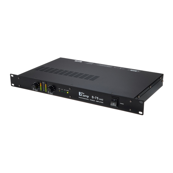
Connections and controls Connections and controls Front panel S-75 • S-100 • S-150... - Page 14 Connections and controls 1 CH-1: Input level controller for channel 1 Use the input level controllers CH-1 and CH-2 (4) on the front panel to control the signal amplification in the respective channel. If possible, turn this control fully to the right stop (= 0 dB attenuation) for optimal headroom.
- Page 15 6 BR: Indicator for mono operation in bridged mode Please read more about the available operating modes in chapter . 7 PAR: Indicator for mono operation in parallel mode Please read more about the available operating modes in chapter . S-75 • S-100 • S-150...
- Page 16 Connections and controls 8 POWER: Power indicator light Lights up green when the unit is turned on. In standby mode, the LED lights red. When the unit receives a signal again, it switches back to normal mode and the LED lights green again.
- Page 17 Connections and controls Rear panel S-75 • S-100 • S-150...
- Page 18 Connections and controls 10 Mains connector with fuse holder Connect the supplied power cord here and supply the device with mains voltage. 11 ERP ON | OFF This switch enables/disables the standby feature. If enabled, the unit automatically enters the standby mode when no input signal is present for at least fifteen minutes.
- Page 19 Connect the line-level signals to be amplified to the 1/4" balanced TRS phone jack input of Channel 2 using a 1/4" phone jack cable. 19 CH-2 Connect the line-level signals to be amplified to the XLR input of Channel 2 using a XLR cable. S-75 • S-100 • S-150...
- Page 20 Connections and controls 20 0.77V | 1.4V | 26dB The input level at which the power amplifier delivers its rated output power can be switched between 0,775 V and 1,4 V . Often multiple amplifiers are used simultaneously. In this case, switch to the "26 dB" position, the signal will then be amplified by all amps equally.
-
Page 21: Installation And Starting Up
Electric shock caused by high voltages at the power amplifier output The output voltages of modern high-performance amplifiers may result in death or serious injury. Never touch the bare ends of loudspeaker cables when the amplifier is on. S-75 • S-100 • S-150... - Page 22 When installing the power amplifier into a rack, you should place it in the lowest position, and further equipment such as pre-amplifiers in the highest position. Models S-75 and S-100 Rack mounting The unit has been designed for rack mounting in a standard 19-inch rack; it occupies one rack unit.
- Page 23 Installation and starting up Model S-150 Rack mounting The device has been designed for rack mounting in a standard 19-inch rack; it occupies two rack units. S-75 • S-100 • S-150...
-
Page 24: Tips On Handling Speakers
Installation and starting up 5.1 Tips on handling speakers We recommend you to set up the speakers in a way, that the sound signals can reach the audi‐ ence unobstructedly. It will often be helpful to mount the speakers on tripods. Thus, the sound will be evenly spread with maximum range throughout the audience area. -
Page 25: More Useful Tips
Parallel mode The two amplifier channels receive the same input signal from channel CH1 and loudspeakers are con‐ nected to each amplifier, the volume for both outputs is controlled by the volume control of CH1. S-75 • S-100 • S-150... - Page 26 Example: If you have two loudspeakers with the same impedance, their impedance doubles if they are connected in a series, their impedance halves if they are connected in parallel. For detailed information related to this topic please refer to our Online Guide ‘PA Speakers’ (www.thomann.de). power amplifier...
-
Page 27: Technical Specifications
Maximum input level 21 dBV / 9 V Input impedance, active balanced 20 kΩ Signal-to-noise ratio, A-weighted, RMS > 80 dB > 85 dB Crosstalk @ rated power, 8 Ω, 1 kHz > 70 dB S-75 • S-100 • S-150... - Page 28 Technical specifications Model no. S-75 S-100 S-150 Damping factor, f=1 kHz, 8 Ω > 150 dB Slew rate 35 V/µs 40 V/µs Protection circuits Short circuit current limit, DC voltage fault, fuse for power supply, limiter, temperature, mains transients Indicator lights...
-
Page 29: Plug And Connection Assignment
In addition to the conduc‐ tors ‘Ground’ and ‘Signal’, in a balanced transmission a second core is added. This also transfers the signal, but phase-shifted by 180°. S-75 • S-100 • S-150... - Page 30 Plug and connection assignment Since the interference affects both cores equally, by subtracting the phase-shifted signals, the interfering signal is completely neutralized. The result is a pure signal without any noise inter‐ ference. 1/4" TS phone plug (mono, unbalanced) Signal Ground, shielding 1/4"...
- Page 31 Plug and connection assignment 1/4" TRS phone plug (stereo, unbalanced) Signal (left) Signal (right) Ground 1/4" TS phone plug (mono, unbalanced) Signal Ground S-75 • S-100 • S-150...
- Page 32 Plug and connection assignment 3.5 mm TRS phone plug (mono, balanced) Signal (in phase, +) Signal (out of phase, –) Ground Three-pole 1/8" mini phone jack (stereo, unbalanced) Signal (left) Signal (right) Ground, shielding power amplifier...
- Page 33 Plug and connection assignment XLR plug (balanced) Ground, shielding Signal (in phase, +) Signal (out of phase, –) XLR plug (unbalanced) Ground, shielding Signal Bridged to pin 1 S-75 • S-100 • S-150...
- Page 34 Plug and connection assignment NL4 mounting connectors 1, + Signal 1 (in phase) 1, – Signal 1 (180 degree phase shift) 2, + Signal 2 (in phase) 2, – Signal 2 (180 degree phase shift) power amplifier...
-
Page 35: Cleaning
The fan grids of the device must be cleaned on a regular basis to remove dust and dirt. Before cleaning, switch off the device and disconnect AC-powered devices from the mains. Use a lint- free damp cloth for cleaning. Never use solvents or alcohol for cleaning. S-75 • S-100 • S-150... -
Page 36: Protecting The Environment
Protecting the environment Protecting the environment Disposal of the packaging mate‐ rial For the transport and protective packaging, environmentally friendly materials have been chosen that can be supplied to normal recycling. Ensure that plastic bags, packaging, etc. are properly disposed of. Do not just dispose of these materials with your normal household waste, but make sure that they are collected for recycling. - Page 37 Notes S-75 • S-100 • S-150...
- Page 38 Notes power amplifier...
- Page 40 Musikhaus Thomann e.K. · Treppendorf 30 · 96138 Burgebrach · Germany · www.thomann.de...
Need help?
Do you have a question about the S-75 and is the answer not in the manual?
Questions and answers