Table of Contents
Advertisement
Quick Links
Advertisement
Table of Contents

Related Manuals for thomann the t.amp S-75 MK II


Summary of Contents for thomann the t.amp S-75 MK II
- Page 1 S-75 MK II, S-100 MK II, S-150 MK II Power Amplifier...
- Page 2 Thomann GmbH Hans-Thomann-Straße 1 96138 Burgebrach Germany Telephone: +49 (0) 9546 9223-0 Internet: www.thomann.de 24.08.2023, ID: 141140, 144356, 141141 (V6)
-
Page 3: Table Of Contents
Table of contents Table of contents General information..........................5 1.1 Symbols and signal words....................... 5 Safety instructions............................. 7 Features............................... 10 Connections and controls........................11 Installation and starting up........................ 17 5.1 Tips on handling speakers......................19 5.2 Other useful hints..........................20 Technical specifications........................ - Page 4 S-75 MK II, S-100 MK II, S-150 MK II Power Amplifier...
-
Page 5: General Information
Our products and documentation are subject to a process of continuous development. They are therefore subject to change. Please refer to the latest version of the documentation, which is ready for download under www.thomann.de. 1.1 Symbols and signal words In this section you will find an overview of the meaning of symbols and signal words that are used in this document. - Page 6 General information Signal word Meaning DANGER! This combination of symbol and signal word indicates an immediate dangerous situation that will result in death or serious injury if it is not avoided. WARNING! This combination of symbol and signal word indicates a pos‐ sible dangerous situation that can result in death or serious injury if it is not avoided.
-
Page 7: Safety Instructions
Safety instructions Safety instructions Intended use This device amplifies electric audio frequency signals to operate passive speakers. Use the device only as described in this user manual. Any other use or use under other operating con‐ ditions is considered to be improper and may result in personal injury or property damage. No liability will be assumed for damages resulting from improper use. - Page 8 Safety instructions DANGER! Danger to life due to electric current! A short circuit could lead to a fire hazard and risk of death. Always use proper ready-made insulated triple-core mains cable with a safety plug. Do not modify the mains cable or the plug. In case of isolation damage, disconnect immediately the power supply and arrange repair.
- Page 9 Safety instructions NOTICE! Damage to the device due to high voltages! The device can be damaged if it is operated with the incorrect voltage or if high voltage peaks occur. In the worst case, excess vol‐ tages can also cause a risk of injury and fires. Make sure that the voltage specification on the device matches the local power grid before plugging in the device.
-
Page 10: Features
Features Features Output power 2 × 45 W to 250 W (depending on the model) Speaker Twist and terminal connections for speakers All protection circuits incl. soft start Input level switchable from –0 to +4 db Fanless operation Standby function S-75 MK II, S-100 MK II, S-150 MK II Power Amplifier... -
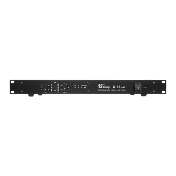
Page 11: Connections And Controls
Connections and controls Connections and controls Front S-75 MK II, S-100 MK II, S-150 MK II Power Amplifier... - Page 12 Connections and controls 1 [CH-1] | Input level controller for channel 1 Use the input level controllers CH-1 and CH-2 (4) on the front panel to control the signal amplification in the respec‐ tive channel. If possible, turn this control fully to the right stop (= 0 dB attenuation) for optimal headroom. Profes‐ sional power amplifiers then output their rated power, if the input voltage is 0.775 V or 1.4 V (depending on the posi‐...
- Page 13 Connections and controls 7 [PAR] | Indicator for mono operation in parallel mode Please read more about the available operating modes in chapter Ä ‘Possible operation modes’ on page 20. 8 [POWER] | Power indicator light Lights up green when the device is turned on. In standby mode, the LED lights up red. As soon as the unit receives a signal, it switches back to normal mode and the LED will light up green again.
- Page 14 Connections and controls Back OUTPUT INPUT F:T5AL 250V (230V~) F:T10AL 250V (115V~) 115V/230V ~, 50/60Hz CH-2 CH-1 CH-2 CH-1 OUTPUT CH-2 CH-1 VOLTAGE SELECTION S-150 115V~ 230V~ F:T5AL 250V (230V~) INPUT F:T10AL 250V (115V~) CH-2 CH-1 115V/230V ~, 50/60Hz S-75 MK II, S-100 MK II, S-150 MK II Power Amplifier...
- Page 15 Connections and controls 10 Mains connector with fuse holder Connect the supplied power cord here and supply the device with mains voltage. 11 [ERP ON | OFF] | On / off switch for the standby function If the standby function is enabled, the device automatically switches to standby mode after 20 minutes without any input signal.
- Page 16 Connections and controls 19 [CH-2] | Signal input XLR Connect the line-level signal to be amplified to the XLR input of channel 2 using an XLR cable. 20 [0.77V | 1.4V | 26dB] | Operating mode switch The input sensitivity at which the power amplifier delivers its full rated power can be set with this switch between 0.775 V and 1.4 V ).
-
Page 17: Installation And Starting Up
Installation and starting up Installation and starting up Unpack and check carefully there is no transportation damage before using the unit. Keep the equipment packaging. To fully protect the product against vibration, dust and moisture during transportation or storage use the original packaging or your own packaging material suitable for transport or storage, respectively. - Page 18 Installation and starting up DANGER! Risk of death from electrical current! The output voltages of modern high-performance amplifiers may result in death or serious injury. Never touch the bare ends of loudspeaker cables when the amplifier is on. NOTICE! Interference with nearby electrical devices due to magnetic fields! The device generates strong magnetic fields that can interfere with the function of poorly shielded devices.
-
Page 19: Tips On Handling Speakers
Installation and starting up The device is designed for mounting in 19-inch racks, it occupies two rack units (RU). 5.1 Tips on handling speakers We recommend you to set up the speakers in a way, that the sound signals can reach the audi‐ ence unobstructedly. -
Page 20: Other Useful Hints
Installation and starting up 5.2 Other useful hints Possible operation modes Depending on the individual application, the amplifier can be used in different operation modes: Stereo mode The two amplifier channels operate independently of one another, either channel (CH1 and CH2) is amplified and connected to loudspeakers, the volume can be con‐... - Page 21 For detailed information related to this topic please refer to our Online Guide "PA Speakers’" (www.thomann.de). S-75 MK II, S-100 MK II, S-150 MK II...
-
Page 22: Technical Specifications
Technical specifications Technical specifications Model type S-75 S-100 S-150 Amplifier class Input impedance 20 kΩ (active, balanced) Input level 21 dBV / 9 V Output power 8 Ω, stereo 2 × 45 W 2 × 65 W 2 × 85 W 4 Ω, stereo 2 ×... - Page 23 Technical specifications Model type S-75 S-100 S-150 Gain 29 dB/26 dB/ 30 dB/26 dB/ 30.5 dB/26 dB/ 24 dB(0.775 V/26 dB/ 24.5 dB(0.775 V/ 25.5 dB(0.775 V/26 dB/ 1.4 V) 26 dB/1.4 V) 1.4 V) Slew rate 35 V/µs 35 V/µs 40 V/µs Crosstalk @ rated power (1 kHz, 8 Ω) >...
- Page 24 Technical specifications Model type S-75 S-100 S-150 Ambient conditions Temperature range 0 °C…40 °C Relative humidity 20 %…80 % (non-con‐ densing) Further information Model type S-75 S-100 S-150 Power 4 Ω / channel 75 W 100 W 150 W Channels 2 Ω...
-
Page 25: Plug And Connection Assignment
Plug and connection assignment Plug and connection assignment Introduction This chapter will help you select the right cables and plugs to connect your valuable equip‐ ment in such a way that a perfect sound experience is ensured. Please note these advices, because especially in ‘Sound & Light’ caution is indicated: Even if a plug fits into the socket, an incorrect connection may result in a destroyed power amp, a short circuit or ‘just’... - Page 26 Plug and connection assignment 1/4" TS phone plug (mono, unbalanced) Signal Ground, shielding 1/4" TRS phone plug (mono, bal‐ anced) Signal (in phase, +) Signal (out of phase, –) Ground 1/4" TRS phone plug (stereo, unbalanced) Signal (left) Signal (right) Ground S-75 MK II, S-100 MK II, S-150 MK II Power Amplifier...
- Page 27 Plug and connection assignment 1/4" TS phone plug (mono, unbalanced) Signal Ground 3.5 mm TRS phone plug (mono, balanced) Signal (in phase, +) Signal (out of phase, –) Ground Three-pole 1/8" mini phone jack (stereo, unbalanced) Signal (left) Signal (right) Ground, shielding S-75 MK II, S-100 MK II, S-150 MK II Power Amplifier...
- Page 28 Plug and connection assignment XLR plug (balanced) Ground, shielding Signal (in phase, +) Signal (out of phase, –) Shielding on plug housing (option) XLR plug (unbalanced) Ground, shielding Signal Bridged to pin 1 S-75 MK II, S-100 MK II, S-150 MK II Power Amplifier...
- Page 29 Plug and connection assignment Speaker Twist chassis connector 1, + Signal 1 (in phase) 1, – Signal 1 (out of phase) 2, + Signal 2 (in phase) 2, – Signal 2 (out of phase) ö S-75 MK II, S-100 MK II, S-150 MK II Power Amplifier...
-
Page 30: Cleaning
Cleaning Cleaning Fan grids The fan grids of the device must be cleaned of any contamination, such as dust, etc. on a reg‐ ular basis. Before cleaning, switch off the device and disconnect mains-operated devices from the mains. Only use pH-neutral, solvent-free and non-abrasive cleaning agents. Clean the unit with a slightly damp lint-free cloth. -
Page 31: Protecting The Environment
Protecting the environment Protecting the environment Disposal of the packaging mate‐ rial For the transport and protective packaging, environmentally friendly materials have been chosen that can be supplied to normal recycling. Ensure that plastic bags, packaging, etc. are properly disposed of. Do not just dispose of these materials with your normal household waste, but make sure that they are collected for recycling. - Page 32 Notes S-75 MK II, S-100 MK II, S-150 MK II Power Amplifier...
- Page 33 Notes S-75 MK II, S-100 MK II, S-150 MK II Power Amplifier...
- Page 34 Notes S-75 MK II, S-100 MK II, S-150 MK II Power Amplifier...
- Page 36 Musikhaus Thomann · Hans-Thomann-Straße 1 · 96138 Burgebrach · Germany · www.thomann.de...
Need help?
Do you have a question about the the t.amp S-75 MK II and is the answer not in the manual?
Questions and answers