Table of Contents
Advertisement
Advertisement
Table of Contents

Related Manuals for thomann the t.amp S-75


Summary of Contents for thomann the t.amp S-75
- Page 1 S-75 • S-100 • S-150 power amplifier user manual...
- Page 2 Musikhaus Thomann e.K. Treppendorf 30 96138 Burgebrach Germany Telephone: +49 (0) 9546 9223-0 email: info@thomann.de Internet: www.thomann.de 09.12.2011...
-
Page 3: Table Of Contents
Table of contents Table of contents General notes............................... 4 Safety instructions............................. 7 Connections and operating elements................... 12 Installation and starting up........................ 20 4.1 Pin assignment..........................22 4.2 Tips on handling speakers......................26 4.3 More useful tips..........................27 Technical specifications........................29 Protecting the environment...................... -
Page 4: General Notes
General notes General notes This user manual contains important information on the safe operation of the device. Read and follow all safety notes and all instructions. Save this manual for future reference. Make sure that it is available to all persons using this device. If you sell the device to another user, be sure that they also receive this manual. - Page 5 General notes Signal word Meaning DANGER! This combination of symbol and signal word indicates an immediate dangerous situation that will result in death or serious injury if it is not avoided. CAUTION! This combination of symbol and signal word indicates a possible dangerous situation that can result in minor injury if it is not avoided.
- Page 6 General notes Warning signs Type of danger Warning – danger zone. power amplifier...
-
Page 7: Safety Instructions
Safety instructions Safety instructions Intended use Use the device only as described in this user manual. Any other use or use under other oper‐ ating conditions is considered to be improper and may result in personal injury or property damage. No liability will be assumed for damages resulting from improper use. This device may be used only by persons with sufficient physical, sensorial, and intellectual abilities and having corresponding knowledge and experience. - Page 8 Safety instructions DANGER! Electric shock caused by high voltages inside Within the device there are areas where high voltages may be present. Never remove any covers. There are no user-serviceable parts inside. DANGER! Electric shock caused by short-circuit Always use proper ready-made insulated mains cabling (power cord) with a pro‐ tective contact plug.
- Page 9 Safety instructions CAUTION! Possible hearing damage With loudspeakers or headphones connected, the device can produce volume levels that may cause temporary or permanent hearing impairment. Do not operate the device permanently at a high volume level. Decrease the volume level immediately if you experience ringing in your ears or hearing impairment.
- Page 10 Safety instructions NOTICE! Operating conditions This device has been designed for indoor use only. To prevent damage, never expose the device to any liquid or moisture. Avoid direct sunlight, heavy dirt, and strong vibrations. NOTICE! Power supply Before connecting the device, ensure that the input voltage (AC outlet) matches the voltage rating of the device and that the AC outlet is protected by a residual current circuit breaker.
- Page 11 Safety instructions NOTICE! Magnetic fields The device generates strong magnetic fields that can interfere with the function of poorly shielded devices. The strongest magnetic fields are directly above and below the power amplifier. Therefore, never place sensitive devices such as pre- amplifiers, radio transmission systems, or tape decks directly above or below the power amplifier.
-
Page 12: Connections And Operating Elements
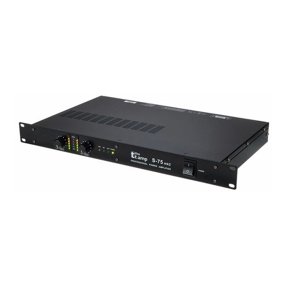
Connections and operating elements Connections and operating elements Front panel power amplifier... - Page 13 Connections and operating elements 1 CH-1: Input level controller for channel 1 Use the input level controllers CH-1 and CH-2 (4) on the front panel to control the signal amplification in the respective channel. If possible, turn this control fully to the right stop (= 0 dB attenuation) for optimal headroom.
- Page 14 Connections and operating elements 5 PRO: Indicator for activated protection circuit This indicator lights up, if one of the following situations arises in one of the chan‐ nels: • 3-5 seconds after switching on, as the speakers are still electrically disconnected from the power amp.
- Page 15 Connections and operating elements 8 POWER: Power indicator light Lights up when the unit is turned on. 9 POWER: On / off switch (9) This switch turns the power on and off. When switching on the protection circuits are activated. After a few seconds you will hear two "clicks" - now the speakers are electrically connected to the amplifier and the device is ready to operate.
- Page 16 Connections and operating elements Rear panel power amplifier...
- Page 17 Connections and operating elements 10 Mains connector with fuse holder Connect the supplied power cord here and supply the device with mains voltage. 11/12 Speaker outputs CH-1/2 Connect speakers to the speaker outputs of channel 1 and 2 using SPK cables (wiring = 1+ 2+ 1–...
- Page 18 Connections and operating elements 16 STE / PAR / BR Use this switch to select the operating mode of the power amp: stereo (STE), par‐ allel (PAR) or bridged (BR). 17 CH-2 Connect the line-level signals to be amplified to the 1/4" balanced TRS phone jack input of Channel 2 using a 1/4"...
- Page 19 Connections and operating elements 20 CH-1 (MONO) Connect the line-level signals to be amplified to the XLR input of Channel 1 using a XLR cable. 21 CH-1 (MONO) Connect the line-level signals to be amplified to the 1/4" balanced TRS phone jack input of Channel 1 using a 1/4"...
-
Page 20: Installation And Starting Up
Installation and starting up Installation and starting up Unpack and check carefully there is no transportation damage before using the unit. Establish all connections as long as the unit is switched off. Use the shortest possible high- quality cables for all connections. DANGER! Electric shock caused by high voltages at the power amplifier output The output voltages of modern high-performance amplifiers may result in death... - Page 21 Installation and starting up NOTICE! Magnetic fields The device generates strong magnetic fields that can interfere with the function of poorly shielded devices. The strongest magnetic fields are directly above and below the power amplifier. Therefore, never place sensitive devices such as pre- amplifiers, radio transmission systems, or tape decks directly above or below the power amplifier.
-
Page 22: Pin Assignment
Installation and starting up Model S-150 Rack mounting The device has been designed for rack mounting in a standard 19-inch rack; it occupies two rack units. 4.1 Pin assignment You can use XLR and phone jack connectors with either balanced or unbalanced wiring. power amplifier... - Page 23 Installation and starting up XLR connection for signal in and XLR mounting sockets provided for signal inputs. XLR mounting plugs provided for signal out‐ outputs puts. Drawings and descriptions explain the pin assignment. Balanced wiring: Ground, shielding Positive signal (+) Negative signal (–) Unbalanced wiring: Ground, shielding...
- Page 24 Installation and starting up 1/4" connectors for signal in and Drawings and descriptions explain the pin assignment of 1/4" connectors. outputs Unbalanced wired 1/4" TS jack: Signal Ground, shielding Unbalanced wired 1/4" TRS jack: Signal Ground, shielding power amplifier...
- Page 25 Installation and starting up Balanced wired 1/4" TRS jack: 1 (Tip) Positive signal (+) 2 (Ring) Negative signal (–) 3 (Sleeve) Ground, shielding S-75 • S-100 • S-150...
-
Page 26: Tips On Handling Speakers
Installation and starting up 4.2 Tips on handling speakers We recommend you to set up the speakers in a way, that the sound signals can reach the audi‐ ence unobstructedly. It will often be helpful to mount the speakers on tripods. Thus, the sound will be evenly spread with maximum range throughout the audience area. -
Page 27: More Useful Tips
Installation and starting up 4.3 More useful tips Possible operation modes Depending on the individual application, the amplifier can be used in different operation modes: Stereo mode The two amplifier channels operate independently of one another, either channel (CH1 and CH2) is amplified and connected to loudspeakers, the volume can be controlled separately for the two outputs. - Page 28 Example: If you have two loudspeakers with the same impedance, their impedance doubles if they are connected in a series, their impedance halves if they are connected in parallel. For detailed information related to this topic please refer to our Online Guide ‘PA Speakers’ (www.thomann.de). power amplifier...
-
Page 29: Technical Specifications
Technical specifications Technical specifications Model no. S-75 S-100 S-150 Output power stereo 8 Ω 2 x 45 W 2 x 65 W 2 x 85 W stereo 4 Ω 2 x 75 W 2 x 100 W 2 x 150 W bridged 8 Ω... - Page 30 Technical specifications Model no. S-75 S-100 S-150 Damping factor, f=1 kHz, 8 Ω > 150 dB Slew rate 35 V/µs 40 V/µs Protection circuits Short circuit current limit, DC voltage fault, fuse for power supply, limiter, temperature, mains transients Indicator lights Power (green), protection (yellow), clipping (red), bridged mode operation (green), parallel mode operation (green) Cooling...
-
Page 31: Protecting The Environment
Protecting the environment Protecting the environment Disposal of the packaging mate‐ rial For the transport and protective packaging, environmentally friendly materials have been chosen that can be supplied to normal recycling. Ensure that plastic bags, packaging, etc. are properly disposed of. Do not just dispose these materials with your normal household waste, but make sure that they are fed to a recovery. - Page 32 Notes power amplifier...
- Page 33 Notes S-75 • S-100 • S-150...
- Page 34 Notes power amplifier...
- Page 36 Musikhaus Thomann e.K. · Treppendorf 30 · 96138 Burgebrach · Germany · www.thomann.de...
Need help?
Do you have a question about the the t.amp S-75 and is the answer not in the manual?
Questions and answers