Table of Contents
Advertisement
Advertisement
Table of Contents

Related Manuals for thomann t.amp E-400


Summary of Contents for thomann t.amp E-400
- Page 1 E-400, E-800, E-1200, E-1500 power amplifier user manual...
- Page 2 Musikhaus Thomann Thomann GmbH Hans-Thomann-Straße 1 96138 Burgebrach Germany Telephone: +49 (0) 9546 9223-0 E-mail: info@thomann.de Internet: www.thomann.de 23.04.2019, ID: 173888_173889_460282_460283...
-
Page 3: Table Of Contents
Table of contents Table of contents General information..........................4 1.1 Further information........................... 5 1.2 Notational conventions........................6 1.3 Symbols and signal words....................... 6 Safety instructions............................. 8 Features............................... 13 Installation and starting up........................ 14 Connections and operating elements................... 18 Technical specifications........................29 Plug and connection assignment.................... -
Page 4: General Information
Our products and user manuals are subject to a process of continuous development. We there‐ fore reserve the right to make changes without notice. Please refer to the latest version of the user manual which is ready for download under www.thomann.de. power amplifier... -
Page 5: Further Information
General information 1.1 Further information On our website (www.thomann.de) you will find lots of further information and details on the following points: Download This manual is also available as PDF file for you to download. Use the search function in the electronic version to find the topics of Keyword search interest for you quickly. -
Page 6: Notational Conventions
General information 1.2 Notational conventions This manual uses the following notational conventions: Letterings The letterings for connectors and controls are marked by square brackets and italics. Examples: [VOLUME] control, [Mono] button. 1.3 Symbols and signal words In this section you will find an overview of the meaning of symbols and signal words that are used in this manual. - Page 7 General information Signal word Meaning DANGER! This combination of symbol and signal word indicates an immediate dangerous situation that will result in death or serious injury if it is not avoided. CAUTION! This combination of symbol and signal word indicates a pos‐ sible dangerous situation that can result in minor injury if it is not avoided.
-
Page 8: Safety Instructions
Safety instructions Safety instructions Intended use This device amplifies electric audio frequency signals to operate passive speakers. Use the device only as described in this user manual. Any other use or use under other operating con‐ ditions is considered to be improper and may result in personal injury or property damage. No liability will be assumed for damages resulting from improper use. - Page 9 Safety instructions DANGER! Electric shock caused by high voltages inside Within the device there are areas where high voltages may be present. Never remove any covers. There are no user-serviceable parts inside. Do not use the device if covers, protectors or optical components are missing or damaged.
- Page 10 Safety instructions CAUTION! Possible hearing damage With loudspeakers or headphones connected, the device can produce volume levels that may cause temporary or permanent hearing impairment. Do not operate the device permanently at a high volume level. Decrease the volume level immediately if you experience ringing in your ears or hearing impairment.
- Page 11 Safety instructions NOTICE! Operating conditions This device has been designed for indoor use only. To prevent damage, never expose the device to any liquid or moisture. Avoid direct sunlight, heavy dirt, and strong vibrations. NOTICE! Power supply Before connecting the device, ensure that the input voltage (AC outlet) matches the voltage rating of the device and that the AC outlet is protected by a residual current circuit breaker.
- Page 12 Safety instructions NOTICE! Magnetic fields The device generates strong magnetic fields that can interfere with the function of poorly shielded devices. The strongest magnetic fields are directly above and below the power amplifier. Therefore, never place sensitive devices such as pre- amplifiers, radio transmission systems, or tape decks directly above or below the power amplifier.
-
Page 13: Features
Features Features Low installation depth 2 × 190 W @ 4 Ω, 2 × 120 W @ 8 Ω (item no. 173888) 2 × 500 W @ 4 Ω, 2 × 350 W @ 8 Ω (item no. 173889) 2 × 1200 W @ 4 Ω, 2 × 800 W @ 8 Ω (item no. 460282) 2 ×... -
Page 14: Installation And Starting Up
Installation and starting up Installation and starting up Unpack and check carefully there is no transportation damage before using the unit. Keep the equipment packaging. To fully protect the product against vibration, dust and moisture during transportation or storage use the original packaging or your own packaging material suitable for transport or storage, respectively. - Page 15 Installation and starting up NOTICE! Magnetic fields The device generates strong magnetic fields that can interfere with the function of poorly shielded devices. The strongest magnetic fields are directly above and below the power amplifier. Therefore, never place sensitive devices such as pre- amplifiers, radio transmission systems, or tape decks directly above or below the power amplifier.
- Page 16 Installation and starting up Possible operation modes Depending on the individual application, the amplifier can be used in different operation modes: Stereo mode The two amplifier channels operate independently of one another, either channel (A and B) is amplified and connected to loudspeakers, the volume can be controlled separately for the two outputs.
- Page 17 For detailed information related to this topic please refer to our Online Guide ‘PA Speakers’ (www.thomann.de). Rack mounting The device has been designed for rack mounting in a standard 19-inch rack; it occupies two rack units.
-
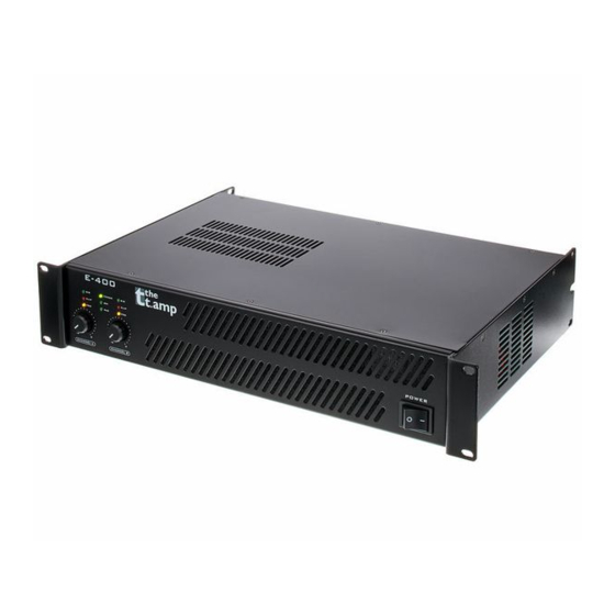
Page 18: Connections And Operating Elements
Connections and operating elements Connections and operating elements Front panel power amplifier... - Page 19 Connections and operating elements 1 [POWER] Mains switch. Turns the device on and off. 2 LED panel [SIG] Indicates the presence of an input signal. [CLIP] Lights under the following conditions: Channel overload Reduce in this case the volume until the LED goes out. Output short circuit Turn off the device immediately, correct the short circuit and turn on the device again.
- Page 20 Connections and operating elements [PAR] Lights when the device is operated in parallel mode. [BR] Lights when the device is operated in bridged mode. 3, 4 [CHANNEL A], Volume control for the respective channel [CHANNEL B] power amplifier...
- Page 21 Connections and operating elements Rear panel E-400 E-400, E-800, E-1200, E-1500...
- Page 22 Connections and operating elements 5 IEC chassis plug with fuse holder 6 [ON] [OFF] [STANDBY] On / off switch for standby function. If the standby function is enabled, the device automatically switches to standby mode after fifteen minutes without any input signal. 7, 8 [OUTPUT] Output channel B, A Speaker Twist chassis connector for speaker output (1+, 2+: positive;...
- Page 23 Connections and operating elements 11 Selector switch for operating mode [PAR]: Parallel mode [STE]: Stereo mode [BR]: Bridged mode 12 Selector switch for input sensitivity 13, 14 [INPUT] Input channel B, A XLR chassis socket ¼-inch (6.35-mm) jack (balanced or unbalanced) RCA socket E-400, E-800, E-1200, E-1500...
- Page 24 Connections and operating elements Rear panel E-800 power amplifier...
- Page 25 Connections and operating elements 15 Power cord 16 [ON] [OFF] [STANDBY] On / off switch for standby function. If the standby function is enabled, the device automatically switches to standby mode after fifteen minutes without any input signal. 17 [BREAKER] Resettable fuse.
- Page 26 Connections and operating elements 21 [GROUND] [LIFT] Ground / lift switch. If hum is caused by a ground loop, you can use this switch to disconnect the connection between the earth pin of the device and the signal ground of the device. 23 [LIMITER] Limits the output level so that the maximum distortion is 5%.
- Page 27 Connections and operating elements Rear panel E-1200, E-1500 E-400, E-800, E-1200, E-1500...
- Page 28 Connections and operating elements 27 IEC panel plug 28, 29 [OUTPUT] Output channel B, A Speaker Twist chassis connector for speaker output (1+, 2+: positive; 1–, 2–: negative) Screw terminals 30, 32 [INPUT] Input channel B, A XLR chassis socket (male) XLR chassis socket (female) 31 Selector switch for operating mode [PAR]: Parallel mode...
-
Page 29: Technical Specifications
Technical specifications Technical specifications E-400, E-800 E-400 (item no. 173888) E-800 (item no. 173889) Amp class H, 2 steps Input connections 1 × IEC panel plug C14 2 × XLR socket, 3-pin 2 × XLR socket, 3-pin 2 × 1/4" phone socket 2 ×... - Page 30 Technical specifications E-400 (item no. 173888) E-800 (item no. 173889) 4 Ω, stereo: 2 × 190 W RMS 4 Ω, stereo: 2 × 500 W RMS Frequency response 20 Hz … 20 kHz (0 / –3 dB), ±1 dB 20 Hz … 20 kHz (0 / –3 dB), ±1 dB Signal-to-noise ratio >...
- Page 31 Technical specifications E-400 (item no. 173888) E-800 (item no. 173889) Dimensions (W × H × D) 482 mm × 88 mm × 317 mm 482 mm × 88 mm × 375 mm Weight 8.3 kg 11.3 kg Ambient conditions Temperature range 0 °C…40 °C Relative humidity 50 %, non-condensing...
- Page 32 Technical specifications E-1200 (item no. 460282) E-1500 (460283) 4 × terminal clamp 4 × terminal clamp Output power 8 Ω, stereo: 2 × 800 W RMS 8 Ω, stereo: 2 × 950 W RMS 4 Ω, stereo: 2 × 1200 W RMS 4 Ω, stereo: 2 ×...
- Page 33 Technical specifications E-1200 (item no. 460282) E-1500 (460283) 2 × 120 W @ 8 Ω 2 × 350 W @ 8 Ω Operating supply voltage 230 V 50 Hz 230 V 50 Hz Dimensions (W × H × D) 482 mm × 88 mm × 362 mm 482 mm ×...
-
Page 34: Plug And Connection Assignment
Plug and connection assignment Plug and connection assignment Introduction This chapter will help you select the right cables and plugs to connect your valuable equip‐ ment in such a way that a perfect sound experience is ensured. Please note these advices, because especially in ‘Sound & Light’ caution is indicated: Even if a plug fits into the socket, an incorrect connection may result in a destroyed power amp, a short circuit or ‘just’... - Page 35 Plug and connection assignment Since the interference affects both cores equally, by subtracting the phase-shifted signals, the interfering signal is completely neutralized. The result is a pure signal without any noise inter‐ ference. 1/4" TS phone plug (mono, unbalanced) Signal Ground, shielding 1/4"...
- Page 36 Plug and connection assignment 1/4" TRS phone plug (stereo, unbalanced) Signal (left) Signal (right) Ground XLR plug (balanced) Ground, shielding Signal (in phase, +) Signal (out of phase, –) Shielding on plug housing (option) power amplifier...
- Page 37 Plug and connection assignment XLR plug (unbalanced) Ground, shielding Signal Bridged to pin 1 Speaker Twist chassis connector 1, + Signal 1 (in phase) 1, – Signal 1 (out of phase) 2, + Signal 2 (in phase) 2, – Signal 2 (out of phase) E-400, E-800, E-1200, E-1500...
- Page 38 Plug and connection assignment RCA connection Drawing and table indicate the pin assignment of an RCA plug. Signal Ground, shielding power amplifier...
-
Page 39: Cleaning
Cleaning Cleaning Fan grids The fan grids of the device must be cleaned of any contamination, such as dust, etc. on a reg‐ ular basis. Before cleaning, switch off the device and disconnect mains-operated devices from the mains. Only use pH-neutral, solvent-free and non-abrasive cleaning agents. Clean the unit with a slightly damp lint-free cloth. -
Page 40: Protecting The Environment
Protecting the environment Protecting the environment Disposal of the packaging mate‐ rial For the transport and protective packaging, environmentally friendly materials have been chosen that can be supplied to normal recycling. Ensure that plastic bags, packaging, etc. are properly disposed of. Do not just dispose of these materials with your normal household waste, but make sure that they are collected for recycling. -
Page 41: E-400, E-800, E-1200, E
Notes E-400, E-800, E-1200, E-1500... - Page 42 Notes power amplifier...
- Page 44 Musikhaus Thomann · Hans-Thomann-Straße 1 · 96138 Burgebrach · Germany · www.thomann.de...
Need help?
Do you have a question about the t.amp E-400 and is the answer not in the manual?
Questions and answers