TSC TX200 Series User Manual
Thermal transfer / direct thermal bar code printer
Hide thumbs
Also See for TX200 Series:
- Service manual (44 pages) ,
- User manual (59 pages) ,
- Programming manual (434 pages)

Related Manuals for TSC TX200 Series


Summary of Contents for TSC TX200 Series
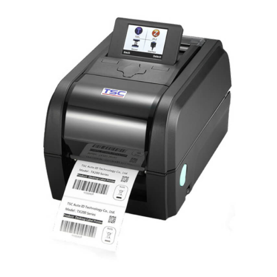
- Page 1 TX200/ TX300/ TX600 Series THERMAL TRANSFER / DIRECT THERMAL BAR CODE PRINTER USER’S MANUAL...
- Page 2 Information in this document is subject to change without notice and does not represent a commitment on the part of TSC Auto ID Technology Co. No part of this manual may be reproduced or transmitted in any form or by any means, for any purpose other than the purchaser’s personal use, without the expressed...
- Page 3 Agency Compliance and Approvals EN 55022, Class B EN 55024 EN 60950-1 FCC part 15B, Class B AS/NZS CISPR 22, Class B UL 60950-1 EN 60950-1 GB 4943.1 GB 9254 GB 17625.1 Wichtige Sicherheits-Hinweise 1. Bitte lesen Sie diese Hinweis sorgfältig durch. 2.
- Page 4 DO NOT throw the battery in municipal waste. The symbol of the crossed out wheeled bin indicates that the battery should not be placed in municipal waste. CAUTION Risk of explosion if battery is replaced by an incorrect type. Dispose of used batteries according to the instructions. “VORSICHT”...
- Page 5 HAZARDOUS MOVING PARTS, KEEP FINGER AND OTHER BODY PARTS AWAY. - iv -...
-
Page 6: Table Of Contents
Contents 1. Introduction ............................1 1.1 Product Introduction ........................1 1.2 Product Features .......................... 2 1.2.1 Printer Standard Features ....................2 1.2.2 Printer Optional Features ....................4 1.3 General Specifications ......................... 5 1.4 Print Specifications ........................5 1.5 Ribbon Specifications ........................5 1.6 Media Specifications ........................ - Page 7 5.2 Gap/Black Mark Calibration, Self-test and Dump Mode ............31 5.3 Printer Initialization ........................35 5.4 Set Black Mark Sensor as Media Sensor and Calibrate the Black Mark Sensor ....... 37 5.5 Set Gap Sensor as Media Sensor and Calibrate the Gap Sensor ..........38 5.6 Skip AUTO.BAS .........................
- Page 8 - vii -...
-
Page 10: Introduction
1.1 Product Introduction Thank you very much for purchasing TSC bar code printer. The TX200 series of thermal transfer desktop barcode printers supports more printing applications than any other printer in its class. With three models available, the four inch... -
Page 11: Product Features
1.2 Product Features 1.2.1 Printer Standard Features The printer offers the following standard features. 200 dpi 300 dpi 600 dpi Product standard feature model model model ○ ○ ○ Thermal transfer/ or direct thermal ○ ○ LED icon panel with 1 button ○... - Page 12 Bar code, graphics/image printing Supported bar code Supported image 1D bar code 2D bar code BITMAP, BMP, PCX Code128 subsets CODABLOCK F A.B.C, Code128UCC, mode, (Max. 256 colors EAN128, Interleave 2 DataMatrix, graphics) of 5, Code 39, Code Maxicode, PDF- 93, EAN-13, EAN-8, 417, Aztec, Codabar, POSTNET,...
-
Page 13: Printer Optional Features
ISO-8859-9: Turkish ISO-8859-10: Nordic ISO-8859-15: Latin-9 UTF-8 1.2.2 Printer Optional Features The printer offers the following optional features. User Dealer Factory Product option feature option option option ○ Peel-off kit Regular cutter (full cut guillotine cutter) Paper thickness: 0.06~ 0.19 mm ○... -
Page 14: General Specifications
1.3 General Specifications General 200 dpi 300 dpi 600 dpi Specifications model model model 226 mm(W) x 200 mm(H) x Physical dimensions 226 mm(W) x 198 mm(H) x 332 mm(D) 332 mm(D) Weight 3.70 kg (8.16 lbs) 4.03 kg ( 8.89 lbs) Mechanism Clamshell with Double-walled plastic External power adapter... -
Page 15: Media Specifications
1.6 Media Specifications 200 dpi 300 dpi 600 dpi Media Specifications model model model Media roll capacity Max. 5” OD Media core diameter 1” & 1.5” ID core Media type Continuous, die-cut, black mark, external fan-fold, notch Outside wound/ Inside wound Media wound type For inside wound media, the max. -
Page 16: Operations Overview
2. Operations Overview 2.1 Unpacking and Inspection This printer has been specially packaged to withstand damage during shipping. Please carefully inspect the packaging and printer upon receiving the bar code printer. Please retain the packaging materials in case you need to reship the printer. Unpacking the printer, the following items are included in the carton. -
Page 17: Printer Overview
2.2 Printer Overview 2.2.1 Front View LED indicators Feed/ Pause button Paper exit chute Top cover open lever Power switch - 8 -... -
Page 18: Interior View
2.2.2 Interior view Ribbon rewind gear Gap sensor (receiver) Media holder Ribbon access cover Ribbon rewind hub Print head Ribbon supply hub Media cover Media holder locking switch Media guides Platen roller Black mark sensor Media guide adjustment button Gap sensor (transmitter) - 9 -... -
Page 19: Rear View
2.2.3 Rear View inter face Power jack socket RS-232C interface inte Ethernet interface * Micro SD card socket USB interface USB host Centronics interface External label entrance chute The interface picture here is for reference only. Please refer to the product specification for the interfaces availability. -
Page 20: Operator Control
2.3 Operator Control 2.3.1 LED Indication and Key Status Status Indication Indication Printer is ready Other errors Blinking Pause Out of paper Erasing memory Blinking Paper jam Blinking Downloading file Out of ribbon Blinking Need to clear print head Blinking Ribbon near end Print head open Blinking... -
Page 21: Setup
3. Setup 3.1 Setting up the printer 1. Place the printer on a flat, secure surface. 2. Make sure the power switch is off. 3. Connect the printer to the computer with the provided USB cable. 4. Plug the power cord into the AC power cord socket at the rear of the printer, and then plug the power cord into a properly grounded power outlet. -
Page 22: Loading The Ribbon
3.2 Loading the Ribbon Open the printer’s top cover by pulling the top cover open levers located on each side of the printer and lifting the top cover to the maximum open angle. Open the ribbon access cover and the media cover. - Page 23 Install the paper core right side onto the rewind hub first then align the notches on the left side and mount onto the spokes. Note: The yellow part of spindle is in left side. Insert the ribbon spindle into the ribbon core.
- Page 24 Stick the ribbon onto the ribbon rewind paper core. Turn the ribbon rewind gear until the ribbon plastic leader is thoroughly wound. Close the ribbon access cover and the top cover. Loading path for ribbon - 15 -...
-
Page 25: Loading The Media
3.3 Loading the Media 3.3.1 Loading the Media 1. Open the printer top cover by pulling the tabs located on each side towards the front of the printer then lift the top cover to the maximum open angle. 2. Separate and hold open the media holders. - Page 26 4. Place the paper, printing side face up, through the media sensor and place the label leading edge onto the platen roller. 5. Move the media guides to fit the label width by pushing the media guide adjustment button. PUSH 6.
- Page 27 Loading path for media - 18 -...
-
Page 28: Loading Media In Cutter Mode (Option)
3.3.2 Loading Media in Cutter Mode (Option) 1. Please refer to section 3.3.1 to feed the paper, printing side face up, through the paper guide and pass over the platen. 2. Lead the paper through the cutter paper opening. 3. Move the media guides to fit the label width by pushing the media guide adjustment button. -
Page 29: Loading Media In Peel-Off Mode (Option)
3.3.3 Loading Media in Peel-off Mode (Option) 1. Please refer to section 3.3.1 to feed the paper, printing side face up, through the paper guide and pass over the platen. 2. Move the media guides to fit the label width by pushing the media guide adjustment button. - Page 30 6. Close the peel-off cover and printer cover. Printer is ready for peel-off mode. 7. Print a label for test. - 21 -...
-
Page 31: Diagnostic Tool
4. Diagnostic Tool TSC’s Diagnostic Utility is an integrated tool incorporating features that enable you to explore a printer’s settings/status; change a printer’s settings; download graphics, fonts and firmware; create a printer bitmap font; and send additional commands to a printer. -
Page 32: Printer Function
4.2 Printer Function 1. Connect the printer and computer with a cable. 2. Select the PC interface connected with bar code printer. USB cable Other cable The default interface setting is USB interface. If USB interface is connected with printer, no other settings need to be changed in the interface field. -
Page 33: Setting Ethernet By Diagnostic Tool
4.3 Setting Ethernet by Diagnostic Tool The Diagnostic Utility is enclosed in the CD disk \Utilities directory. Users can use Diagnostic Tool to setup the Ethernet by RS-232, USB and Ethernet interfaces. The following contents will instruct users how to configure the Ethernet by these three interfaces. - Page 34 2. Turn on the printer power. 3. Start the Diagnostic Utility by double clicks on the icon. 4. Select “COM” as interface then click on the “Setup” button to setup the serial port baud rate, parity check, data bits, stop bit and flow control parameters. 5.
-
Page 35: Using Ethernet Interface To Setup Ethernet Interface
4.3.3 Using Ethernet interface to setup Ethernet interface 1. Connect the computer and the printer to the LAN. 2. Turn on the printer power. 3. Start the Diagnostic Utility by double clicks on the icon. 4. Select “Ethernet” as the interface then click on the “Setup” button to setup the IP address, subnet mask and gateway for the on board Ethernet. - Page 36 5. Click the “Discover Device” button to explore the printers that exist on the network. 6. Select the printer in the left side of listed printers, the correspondent IP address will be shown in the right side “IP address/Printer Name” field. 7.
- Page 37 Web setup button Except to use the Diagnostic Utility to setup the printer, you can also explore and configure the printer settings and status or update the firmware with the IE or Firefox web browser. This feature provides a user friendly setup interface and the capability to manage the printer remotely over a network. - 28 -...
-
Page 38: Power-On Utilities
5. Power-on Utilities There are six power-on utilities to set up and test printer hardware. These utilities are activated by pressing FEED button then turning on the printer power simultaneously and release the button at different status of LED. Please follow the steps below for different power-on utilities. 1. -
Page 39: Ribbon And Gap/Black Mark Sensor Calibration
5.1 Ribbon and Gap/Black Mark Sensor Calibration Gap/black mark sensor sensitivity should be calibrated at the following conditions: 1. A brand new printer 2. Change label stock 3. Printer initialization Please follow the steps below to calibrate the ribbon and gap/black mark sensor. 1. -
Page 40: Gap/Black Mark Calibration, Self-Test And Dump Mode
5.2 Gap/Black Mark Calibration, Self-test and Dump Mode While calibrate the gap/black mark sensor, printer will measure the label length, print the internal configuration (self-test) on label and then enter the dump mode. To calibrate gap or black mark sensor, depends on the sensor setting in the last print job. - Page 41 Self-test Printer will print the printer configuration after gap/black mark sensor calibration. Self-test printout can be used to check if there is any dot damage on the heater element, printer configurations and available memory space. Self-test printout Model name F/W version Firmware checksum Printer S/N...
- Page 42 Numbers of download files Total & available memory space Print head check pattern - 33 -...
-
Page 43: Dump Mode
Dump mode Printer will enter dump mode after printing printer configuration. In the dump mode, all characters will be printed in 2 columns as following. The left side characters are received from your system and right side data are the corresponding hexadecimal value of the characters. It allows users or engineers to verify and debug the program. -
Page 44: Printer Initialization
5.3 Printer Initialization Printer initialization is used to clear DRAM and restore printer settings to defaults. The only one exception is ribbon sensitivity, which will note be restored to default. Printer initialization is activated by the following procedures. 1. Turn off the power switch. 2. - Page 45 Offset Tear Mode Peel off Mode Cutter Mode Serial Port Settings 9600 bps, none parity, 8 data bits, 1 stop bit Code Page Country Code Clear Flash Memory IP Address DHCP - 36 -...
-
Page 46: Set Black Mark Sensor As Media Sensor And Calibrate The Black Mark Sensor
5.4 Set Black Mark Sensor as Media Sensor and Calibrate the Black Mark Sensor Please follow the steps as below. 1. Turn off the power switch. 2. Hold on the button then turn on the power switch. 3. Release the button when LED turns red and 5 blinks. -
Page 47: Set Gap Sensor As Media Sensor And Calibrate The Gap Sensor
5.5 Set Gap Sensor as Media Sensor and Calibrate the Gap Sensor Please follow the steps as below. 1. Turn off the power switch. 2. Hold on the button then turn on the power switch. 3. Release the button when LED turns green and 5 blinks. -
Page 48: Skip Auto.bas
5.6 Skip AUTO.BAS TSPL2 programming language allows user to download an auto execution file to flash memory. Printer will run the AUTO.BAS program immediately when turning on printer power. The AUTO.BAS program can be interrupted without running the program by the power-on utility. Please follow the procedures below to skip an AUTO.BAS program. -
Page 49: Lcd Menu Function
6. LCD Menu Function 6.1 Enter the Menu Press the “Menu” button to enter the main menu. Use the “Cross” button to select the item on main menu. The selected item will turn red. Press the “Feed” button to enter the setting list. Note: This LCD function is optional for TX200 and TX300 series. -
Page 50: Main Menu Overview
6.2 Main Menu Overview There are 8 categories for the main menu. You can easy to set the settings of printer without connecting the computer. Please refer to following sections for more details. Menu File TSPL ZPL2 Sensor Interface Advanced Service Diagnostics Manager... -
Page 51: Tspl2
6.3 TSPL2 This “TSPL2” category can set up the printer settings for TSPL2. Speed Density None Direction Batch Mode Print mode Peeler Mode Offset Cutter Mode Menu TSPL Shift X Cutter Batch Shift Y Reference X Reference Y Code Page Country Item Description... - Page 52 Peeler Mode Enable the label peel off mode. Cutter Mode Enable the label cutter mode. Cutter Batch Cut the label once at the end of the printing job. This item is used to fine tune media stop location. Available setting Offset +000 value is from “+”...
-
Page 53: Zpl2
6.4 ZPL2 This “ZPL2” category can set up the printer settings for ZPL2. Darkness Print Speed Tear Off Tear Off Print Mode Peeler Off Print Width Cutter List Fonts List Images List Formats List Setup Control Prefix Format Prodix Feed Delimiter Char Menu ZPL2... - Page 54 6 (203dpi) Use this item to setup print speed. The each increase or Print Speed 4 (300dpi) decrease is 1 ips. Available setting is from 2 to 6. 3 (600dpi) This item is used to fine tune media stop location. Available Tear Off +000 setting value is from “+”...
- Page 55 label. The range is -9999 to +9999 dots. When reprint mode is enabled, you can reprint the last label Reprint Mode Disabled printer by pressing “UP” button on printer’s control panel. Selects the bitmap scaling factor. The first number is the original Format Convert dots per inch (dpi) value;...
-
Page 56: Sensor
6.5 Sensor This option is used to calibrate the selected sensor. We recommend calibrate the sensor before printing when changing the media. Auto Black Mark Calibration Continuous Manual Setup Black Mark Menu Sensor Continuous Auto Threshold Detect Fixed Maximum Length Advanced Item Description... -
Page 57: Interface
6.6 Interface This option is used to set the printer interface settings. Serial Ethernet Menu Interface Bluetooth Wi-Fi 6.6.1 Serial Comm. This option is used to set the printer RS-232 settings. 1200 bps 2400 bps 4800 bps 9600 bps Baud Rate 19200 bps 38400 bps 57600 bps... -
Page 58: Ethernet
6.6.2 Ethernet Use this menu to configure internal Ethernet configuration check the printer’s Ethernet module status, and reset the Ethernet module. Status Menu Interface Ethernet DHCP Configure Static IP Item Description Default Use this menu to check the Ethernet IP address and Status MAC setting status. -
Page 59: Bluetooth
6.6.3 Bluetooth This option is used to set the printer blustooth settings. Bluetooth Name Menu Interface Bluetooth Bluetooth PIN code Item Description Default Bluetooth This item is used to set the local name for Bluetooth. BT-SPP Name Bluetooth This item is used to set the local PIN code for 0000 Code Bluetooth. -
Page 60: File Manager
6.7 File Manager This feature is used to check the printer available memory and file list. DRAM Menu File Manager FLASH CARD Item Description Use this menu to show, delete and run (.BAS) the files saved in DRAM the printer DRAM memory. Use this menu to show, delete and run (.BAS) the files saved in FLASH the printer Flash memory. -
Page 61: Diagnostics
Menu Diagnostics Print Config. Self-test printout Model name F/W version Firmware checksum Printer S/N TSC configuration file System date System time Printed mileage (meter) Cutting counter Print speed (inch/sec) Print darkness Label size (inch) Gap distance (inch) - Page 62 ZPL setting information Print darkness Print speed (inch/sec) Label size Control prefix Format prefix Delimiter prefix Printer power up motion Printer head close motion Note: ® ZPL is emulating for Zebra language. RS232 serial port configuration Numbers of download files Total &...
-
Page 63: Dump Mode
6.8.2 Dump Mode Captures the data from the communications port and prints out the data received by printer. In the dump mode, all characters will be printed in 2 columns. The left side characters are received from your system and right side data are the corresponding hexadecimal value of the characters. -
Page 64: Print Head
6.8.3 Print Head This feature is used to check print head’s temperature, resistance and bad dots. Menu Diagnostics Print Head 6.8.4 Display This feature is used to check LCD’s color state. Menu Diagnostics Display - 55 -... -
Page 65: Advanced
6.9 Advanced This feature is used to set the printer LCD settings. Display Brightness Menu Advanced Date & Time Language Item Description Display This item is used to setup the brightness for display. Brightness Date & Time display This item is used to setup the date and time on Language display This item is used to setup the language on... -
Page 66: Service
6.10 Service This feature is used to restore printer settings to defaults and checking information for printer. Initialization Menu Service Printer Information Contact Us Item Description Initialization This feature is used to restore printer settings to defaults. Printer This feature is used to check the printer’s serial number, printed Information mileage (m), printed labels (pcs.) and cutting counter. -
Page 67: Troubleshooting
7. Troubleshooting The following guide lists the most common problems that may be encountered when operating this bar code printer. If the printer still does not function after all suggested solutions have been invoked, please contact the tech support service of your purchased reseller or distributor for assistance. - Page 68 - Wait a few seconds let the printer get the communication with the server then check the IP address setting again. * Please reset the wireless device setting. * Select the correct printer port in the driver. * Print head’s harness connector is not well connected with printheat.
- Page 69 * The printer is in Hex Dump * Turn off and on the printer to skip the mode. Irregular printing dump mode. * The RS-232 setting is * Re-set the Rs-232 setting. incorrect. * If the label is moving to the right side, Label feeding is not stable * The media guides do not please move the label guide to left.
-
Page 70: Maintenance
8. Maintenance This session presents the clean tools and methods to maintain your printer. 1. Please use one of following material to clean the printer. Cotton swab Lint-free cloth Vacuum / Blower brush 100% Ethanol or Isopropyl Alcohol 2. -
Page 71: Revise History
Revise History Date Content Editor 2015/4/15 Modify the pictures for moved parts color (green) Camille 2015/4/20 Modify section 3.2 (Printhead module change) Camille - 62 -... - Page 73 9F., No.95, Minquan Rd., Xindian Dist., No.35, Sec. 2, Ligong 1st Rd., Wujie Township, New Taipei City 23141, Taiwan (R.O.C.) Yilan County 26841, Taiwan (R.O.C.) TEL: +886-2-2218-6789 TEL: +886-3-990-6677 FAX: +886-2-2218-5678 FAX: +886-3-990-5577 Web site: www.tscprinters.com E-mail: apac_sales@tscprinters.com TSC Auto ID Technology Co., Ltd. tech_support@tscprinters.com...
Need help?
Do you have a question about the TX200 Series and is the answer not in the manual?
Questions and answers