TSC TTP-245 User Manual
Hide thumbs
Also See for TTP-245:
- Service manual (109 pages) ,
- User manual (34 pages) ,
- Quick installation manual (2 pages)
Table of Contents
Advertisement
Advertisement
Table of Contents

Related Manuals for TSC TTP-245


Summary of Contents for TSC TTP-245
- Page 1 TTP-245/343 THERMAL TRANSFER / DIRECT THERMAL BAR CODE PRINTER USER’S MANUAL...
-
Page 2: Table Of Contents
Contents ................1 OPYRIGHT ECLARATION ....................1 OMPLIANCES 1. Introduction..................1 2. Getting Started ..................1 2.1 Unpacking and Inspection............1 2.2 Equipment Checklist..............1 2.3 Printer Parts...................3 3. Setup....................4 3.1 Setting Up the Printer ..............4 3.2 Loading the Ribbon...............4 3.3 Loading Label Stock ..............6 3.4 External Label Roll Mount Installation (Option) ......8 3.5 Peel-off Module Installation (Option)...........9 3.5.1 Loading the Paper in Peel-off Mode........12 3.6 Cutter Module Installation (Option) ...........14... - Page 3 Update History ..................35...
-
Page 4: Copyright Declaration
Copyright Declaration Information in this subject to change without notice and does not represent a commitment on the part of Taiwan Semiconductor Company. No part of this manual may be reproduced or transmitted in any form by any means, for any purpose other than the purchaser’s personal use, without the expressed written permission of Taiwan Semiconductor Company. - Page 5 8. Dieses das Gerät kann bis zu einer Außentemperatur von maximal 40℃ betieben werden.
-
Page 6: Introduction
This printer provides both thermal transfer and direct thermal printing at user selectable speed of: 2.0, 3.0, 4.0 or 5.0 ips, for TTP-245; 2.0 or 3.0 ips for TTP-343. It accepts roll feed, die-cut, and fan-fold labels for both thermal transfer and direct thermal printing. - Page 7 purchased reseller or distributor. Options External label roll mount Label spindle (3-inch diameter core) Programmable keyboard (KU-007 Plus) Stand-alone LCD keyboard (KP-200) Automatic cutter module Peel off module Internal Ethernet print server External 802.11b/g wireless print server...
-
Page 8: Printer Parts
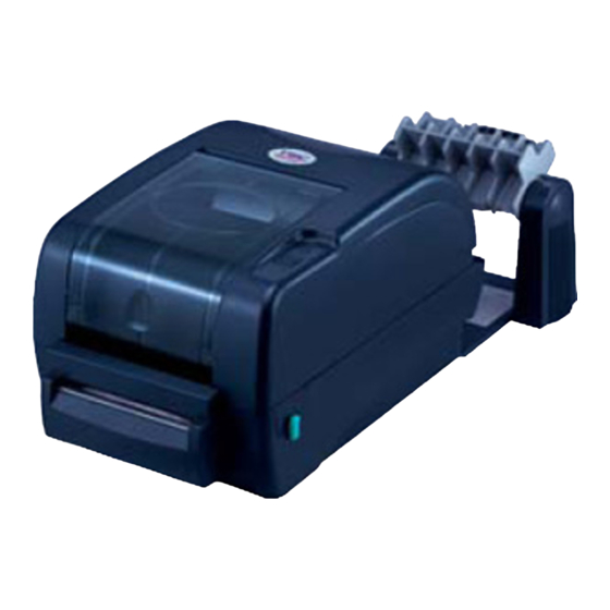
2.3 Printer Parts Clear Window Ribbon Access Cover LED Indicator Feed Button Printer Top Cover Top Cover Open Lever Fig. 1 Top front view 1. USB Interface 2. Centronics Interface 3. RS-232C DB-9 Interface 4. Power Jack 5. Power Switch 6. -
Page 9: Setup
3. Setup 3.1 Setting Up the Printer 1. Place the printer on a flat, secure surface. 2. Make sure the power switch is off. 3. Connect the printer to the computer with the Centronics or USB cable. 4. Plug the power cord into the power supply connector at the rear of the printer, and then plug the power cord into a properly grounded receptacle. - Page 10 Please follow the steps below to install the ribbon into printer. 1. Push down on the ribbon access window to unlatch and open the cover. 2. Place a paper core onto the ribbon rewind spindle. Mount the ribbon rewind paper core on the front hubs. 4.
-
Page 11: Loading Label Stock
Ribbon supply spindle Ribbon Lead Tape Rear Hub Ribbon Rewind Spindle with Paper Core Fig. 5 Ribbon installation (II) 3.3 Loading Label Stock 1. Insert a 1” label spindle into a paper roll ( * f your paper core is 1 inch, remove the 1.5”... - Page 12 Lower Cover Fig. 7 Pull the lever to open the cover 3. Place a roll of paper onto the center of the paper roll mount. 4. Feed the paper, printing side face up, through the Teflon bar and the paper guide and pass over the platen.
-
Page 13: External Label Roll Mount Installation (Option)
Fig. 8 Label installation (II) 3.4 External Label Roll Mount Installation (Option) 1. Attach an external paper roll mount on the bottom of the printer. Fig. 9 Attach the external roll mount to the printer 1. Open the printer top cover by releasing the top cover open levers. The top cover support will hold the printer top cover. -
Page 14: Peel-Off Module Installation (Option)
6. Close the printer top cover by lifting the top cover to the maximum opening angle then push down the top cover gently. Rear Paper Guide Top Cover Support Paper Guide Platen Fig. 11 External roll mount label installation (II) 3.5 Peel-off Module Installation (Option) 1. - Page 15 Top Cover Top Cover Support Screws Flute Lower Inner Screws Cover Lower Cover Fig. 13 Remove 6 screws from lower inner cover 4. Upside down the printer. Remove two screws at the hinge and remove one screw at memory card cover. 5.
- Page 16 Fig. 14 Connect peel-off sensor cable to main board Bezel Mortise Fig. 15 Peel-off sensor cable installation 7. Insert the peel-off tenons into the lower inner cover mortises until tenons snap into places. Lower Inner Cover Roller Lower Cover Tenon Mortise Fig.
-
Page 17: Loading The Paper In Peel-Off Mode
Peel-off panel Roller Fig. 17 Peel-off panel installation (II) Lift up the peel-off panel to the lower cover to close it. 10. Use a screwdriver to screw down whole screws on the lower inner cover and the lower cover. 11. Close the top cover by arranging the top cover support back to the flute and push it forward then close the cover slowly. - Page 18 3. Install the paper roll on the paper roll mount. 4. Open the peel-off panel by pulling it out. Peel-off panel Fig. 19 Open the peel-off panel 5. Feed the paper, printing side facing up, through the paper guide and pass over the platen.
-
Page 19: Cutter Module Installation (Option)
slowly. Note: Pull the label outward tightly after closing the top cover. Fig. 21 Complete label installation for peel-off mode 3.6 Cutter Module Installation (Option) 1. Pull the top cover open levers to open the top cover. 2. Remove the front panel from the lower cover. Lower Cover Fig. - Page 20 Top Cover Top Cover Support Screws Flute Front Panel Screws Lower Inner Cover Lower Cover Fig. 23 Remove 6 screws from lower inner cover 5. Place the printer upside down and unscrew the two screws of the hinge holder on the lower cover.
-
Page 21: Loading Label In Cutter Mode
Lower Inner Cover Fig. 25 Cutter module cable arrangement Cutter Cable Lower Cover Bezel 8. Arrange the lower inner cover back to the lower cover. 9. Install the cutter into the niches of the printer. Cutter Niche Fig. 26 Cutter module installation 10. - Page 22 1. Insert a 1” label spindle into a paper roll. 2. Open the printer top. 3. Install a paper roll on the paper roll mount. 4. Feed the paper, printing side face up, through the paper guide and pass over the platen.
-
Page 23: Instructions To Top Cover Operation
3.7 Instructions to Top Cover Operation Please take care when opening or closing the printer’s top cover by carefully following these instructions. To Open: 1. When facing the front of the printer pull the cover release levers on both sides of printer towards you. - Page 24 Fig. 2 Top cover is fully open and ready to close Fig. 3 Use both hands to close the top cover 5. Do not force the cover! If you are not sure if top cover is fixed at stop position, please do not push top cover to close it or the top cover will be damaged.
-
Page 25: Power On Utilities
4. Power on Utilities There are six power-on utilities to set up and test printer hardware. These utilities are activated by pressing FEED button and by turning on the printer power simultaneously. The utilities are listed as below: Ribbon sensor calibration;Gap/black mark sensor calibration Gap/black mark sensor calibration;Self-test and dump mode Printer initialization Black mark sensor calibration... -
Page 26: Gap/Black Mark Calibration;Self-Test;Dump Mode
4.2 Gap/Black Mark Calibration;Self-test;Dump Mode While calibrate the gap/black mark sensor, printer will measure the label length, print the internal configuration (self-test) and then enter the dump mode. To calibrate gap or black mark sensor, depends on the sensor setting in the last print job. Please follow the steps below to calibrate the sensor. - Page 27 Self-test Printer will print the printer configuration after gap/black mark sensor calibration. Self-test printout can be used to check if there is any dot damage on the heater element, printer configurations and available memory space. Print head check pattern Firmware version Firmware checksum Printed mileage (meter) Serial port configuration...
-
Page 28: Dump Mode
Dump mode Printer will enter dump mode after printing printer configuration. In the dump mode, all characters will be printed in 2 columns as following. The left side characters are received from your system and right side data are the corresponding hexadecimal value of the characters. -
Page 29: Printer Initialization
(5 blinks) solid green Printer configuration will be restore to defaults as below after initialization. Parameter Default setting Speed TTP-245, 127 mm/sec (5 ips) (203DPI) TTP-343, 76 mm/sec (3 ips) (300DPI) Density Label Width 4.25” (108.0 mm) Label Height 2.5”... -
Page 30: Black Mark Sensor Calibration
4.4 Black Mark Sensor Calibration Set black mark sensor as media sensor and calibrate the black mark sensor. Please follow the steps as below. 1. Turn off the power switch. 2. Hold on the button then turn on the power switch. 3. - Page 31 (5 blinks) red/amber (5 blinks) solid green 4. Printer will be interrupted to run the AUTO.BAS program.
-
Page 32: Maintenance
5. Maintenance 5.1 Cleaning Use one or more of the following supplies that meets your needs: Cotton swab Lint-free cloth Vacuum 100% ethanol The cleaning process is described as following Printer Part Method 1. Always turn off the printer before cleaning the print Printer Head head. -
Page 33: Troubleshooting
6. Troubleshooting This section lists the common problems that according to the LED status and other problems you may encounter when operating the printer. Also, it provides solutions. 6.1 LED Status LED Status / Color Printer Status Solution Number Solid Green Green with blinking Pause Red with blinking... -
Page 34: Print Quality
6.2 Print Quality Continuous feeding labels The printer setting may go wrong. Please do the Initialization and Gap/Black Mark Calibration. No print on the label Is the label or ribbon loaded correctly? Follow the instructions in Loading the Paper or Loading the Ribbon. Does the ribbon run out? Follow the instructions in Loading the Ribbon. -
Page 35: Specifications
7. Specifications 7.1 Printer Specifications Item TTP-245 TTP-343 Mechanism Resolution 203 dpi 300 dpi Max. Print Width 108 mm 104 mm Max. Print Length 1000 mm ( 39” ) 420 mm (16.53”) Ribbon Capacity 300 meter with 1” core (Max. OD 67 mm) -
Page 36: Label Stock Specifications
add-on, MSI, PLESSEY, POSTNET, ChinaPOST, ITF-14, EAN-14. 2D Bar code PDF-417, Maxicode, and DataMatrix, QR CODE. Command Set TSPL2 Environment Temperature: 5℃ ~ 40℃. Operation Relative Humidity: 25% ~ 85% (Non Condensing). Temperature: -40℃ ~ 60℃. Storage Relative Humidity: 10% ~ 90% (Non Condensing). 7.2 Label Stock Specifications Item Specification... -
Page 37: Led And Button Operation
8. LED and Button Operation 8.1 LED LED Color Description Green/ Solid This illuminates that the power is on and the device is ready to use. Green/ Flash This illuminates that the system is downloading data from PC to memory and the printer is paused. Amber This illuminates that the system is clearing data from printer. - Page 38 1.Turn off the power switch. Gap/Black Mark 2. Hold on the button then turn on the power switch. Sensor Calibratio, 3. Release the button when LED becomes amber and Label Length blinking. (Any amber will do during the 5 blinks). Measurement, The LED color will be changed as following order.
- Page 39 1. Turn off the power switch. Gap Sensor 2. Hold on the button then turn on the power switch. Calibration 3. Release the button when LED turns red/amber after 5 green/amber blinks. (Any red/amber will do during the 5 blinks). The LED color will be changed as following: Amber red (5 blinks)
-
Page 40: Update History
1. Modify power on utilities section. Camille Pao 2. Modify LED and button operation section. 2006/11/30 1. Modify power on utilities section. Camille Pao 2007/1/25 1. Modify 3.5 section. Camille Pao 2007/4/14 1. Update TSC e-mail address Camille Pao 2. Update 5.5 section: maintenance... - Page 41 TAIWAN SEMICONDUCTOR CO., LTD. 11F, No. 205, Sec. 3, Beishin Rd., Shindian City, Taipei, Taiwan, R.O.C. TEL:+886-2-8913-1588 E-mail:printer_sales@mail.ts.com.tw FAX:+886-2-8913-1808 Technical Support:tech_support@mail.ts.com.tw Website:http://www.tscprinters.com...
Need help?
Do you have a question about the TTP-245 and is the answer not in the manual?
Questions and answers