Table of Contents
Advertisement
Quick Links
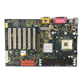
4S845AL
User's Manual Version 1.0
The information presented in this publication has been
made carefully for reliability; however, no responsibility
is assumed for inaccuracies. Specifications are subject
to change without notice.
IBM, PC/AT, and PC/XT are trademarks of
International Business Machines Corporation.
Socket478 is a trademark of Intel Corporation
AWARD is a registered trademark of Phoenix
Software Inc.
MS-DOS and WINDOWS NT are registered
trademarks of Microsoft Corporation.
Trademarks and/or registered trademarks are the
properties of their respective owners.
i
Advertisement
Table of Contents

Related Manuals for Acorp 4S845AL


Summary of Contents for Acorp 4S845AL
- Page 1 4S845AL User's Manual Version 1.0 The information presented in this publication has been made carefully for reliability; however, no responsibility is assumed for inaccuracies. Specifications are subject to change without notice. IBM, PC/AT, and PC/XT are trademarks of International Business Machines Corporation.
- Page 2 Table of Contents Intrnctctinn Intrnctctinn Intrnctctinn Intrnctctinn Intrnctctinn 1. Mnthdranarc Ddrcriotinn 1. Mnthdranarc Ddrcriotinn 1. Mnthdranarc Ddrcriotinn 1. Mnthdranarc Ddrcriotinn 1. Mnthdranarc Ddrcriotinn 1.1 Fdattrdr 1.1.1 Harcward 1.1.1 Snetward 1.1.3 Attachmdntr 1.1 Mnthdranarc Inrtallatinn 1.1.1 Mnthdranarc Mao 1.1.1 Mnthdranarc Layntt 1.3 Mnthdranarc Cnnndctnrr 1.3.1 Frnnt Pandl Cnnndctnr(PANEL( 1.3.1 Flnooy Dirk Cnnndctnr(FDC(...
- Page 3 Table of Contents 1.9 Atcin Staryrtdm 1.9.1 CD-Atcin-IN Cnnndctnr(CDIN1.CDIN1( 1-11 (notinnal( 1.9.1 Tdldohnnd in Cnnndctnr(TAD( 1-13 1.1/ Smart Pandl Nnanarc Cnnndctnr 1.1/.1 Pnrt 8/ Ddatg Ftnctinn(SP-J6( 1-14 1.1/.1 Sdcnnc BINS Cnnndctnr(SP-J1( 1-14 1.1/.3 AUX LINE Cnnndctnr(SP-J5( 1-14 1.1/.4 Frnnt CNM1 Hdacdr Cnnndctnr(SP-J6( 1-15 1.1/.5 Frnnt USB3,4 Hdacdr Cnnndctnr(SP-J8( 1-15...
-
Page 4: Before You Proceed
Before you proceed: Take note of the following precautions before you install device on motherboard: First: before you boot i. Please check up Power supply on page 1-10. ii. Check up DRAM Memory module on page 1-2. iii. Check up AGP card is 1.5V/4X device on page 1-2. Second: Boot your system i. -
Page 5: System Overview
Chaosdr 1 Chaosdr 1 Mnshdranarc Cdrbrhoshnn Mnshdranarc Cdrbrhoshnn Chaosdr 1 Chaosdr 1 Chaosdr 1 Mnshdranarc Cdrbrhoshnn Mnshdranarc Cdrbrhoshnn Mnshdranarc Cdrbrhoshnn Introduction System Overview This manual was written to help you start using this product as quickly and smoothly as possbile. Inside, you will find the answers to solve most problems. -
Page 6: Dram Memory
Chaosdr 1 Chaosdr 1 Mnshdranarc Cdrbrhoshnn Mnshdranarc Cdrbrhoshnn Chaosdr 1 Chaosdr 1 Chaosdr 1 Mnshdranarc Cdrbrhoshnn Mnshdranarc Cdrbrhoshnn Mnshdranarc Cdrbrhoshnn 1.Motherboard Description 1.1 Features 1.1.1 Hardware -400MHz System Interface speed. -Single Socket 478 for Intel P4 up to 2.2GHz or higher(Northwood Processor). -
Page 7: Universal Serial Bus
Chaosdr 1 Chaosdr 1 Mnshdranarc Cdrbrhoshnn Mnshdranarc Cdrbrhoshnn Chaosdr 1 Chaosdr 1 Chaosdr 1 Mnshdranarc Cdrbrhoshnn Mnshdranarc Cdrbrhoshnn Mnshdranarc Cdrbrhoshnn Universal Serial Bus -Supports two back Universal Serial Bus(USB)Ports and two front Universal serial Bus(USB)Ports. Hardware Monitor Function -CPU Fan Speed Monitor. -CPU Temperature Monitor. -
Page 8: Operation System
Chaosdr 1 Chaosdr 1 Mnshdranarc Cdrbrhoshnn Mnshdranarc Cdrbrhoshnn Chaosdr 1 Chaosdr 1 Chaosdr 1 Mnshdranarc Cdrbrhoshnn Mnshdranarc Cdrbrhoshnn Mnshdranarc Cdrbrhoshnn I/O Built-in On Board -Supports one multi-mode Parallel Port. (1)Standard & Bidirection Parallel Port (2)Enhanced Parallel Port (EPP) (3)Extended Capabilities Port -Supports two serial ports, 16550 UART. -
Page 9: Motherboard Installation
Chaosdr 1 Chaosdr 1 Mnshdranarc Cdrbrhoshnn Mnshdranarc Cdrbrhoshnn Chaosdr 1 Chaosdr 1 Chaosdr 1 Mnshdranarc Cdrbrhoshnn Mnshdranarc Cdrbrhoshnn Mnshdranarc Cdrbrhoshnn 1.2 Motherboard Installation 1.2.1 Motherboard Map 1 - 5 1 - 5 1 - 5 1 - 5 1 - 5... -
Page 10: Motherboard Layout
Chaosdr 1 Chaosdr 1 Mnshdranarc Cdrbrhoshnn Mnshdranarc Cdrbrhoshnn Chaosdr 1 Chaosdr 1 Chaosdr 1 Mnshdranarc Cdrbrhoshnn Mnshdranarc Cdrbrhoshnn Mnshdranarc Cdrbrhoshnn 1.2.2 Motherboard Layout T:Mouse JP12 B:KB USB1 COM1 Printer COM2 Intel Speak out GAME1 Line in MIC in AGP SLOT (Only 4X/1.5V Card) PCI0 PCI1... -
Page 11: Motherboard Connectors
Chaosdr 1 Chaosdr 1 Mnshdranarc Cdrbrhoshnn Mnshdranarc Cdrbrhoshnn Chaosdr 1 Chaosdr 1 Chaosdr 1 Mnshdranarc Cdrbrhoshnn Mnshdranarc Cdrbrhoshnn Mnshdranarc Cdrbrhoshnn 1.3 Motherboard Connectors T:Mouse JP12 B:KB USB1 COM1 Printer COM2 Intel Speak out GAME1 Line in MIC in AGP SLOT (Only 4X/1.5V Card) PCI0 PCI1... -
Page 12: Speaker Connector (Speaker)
Chaosdr 1 Chaosdr 1 Mnshdranarc Cdrbrhoshnn Mnshdranarc Cdrbrhoshnn Chaosdr 1 Chaosdr 1 Chaosdr 1 Mnshdranarc Cdrbrhoshnn Mnshdranarc Cdrbrhoshnn Mnshdranarc Cdrbrhoshnn 1.3.1 Front Panel Connector (PANEL) PANEL Connector SPEAKER HD_LED RESET PW_BN EXTSMI SULED KBLOCK PW_LED ATX Power Switch (PW_BN) The system power is controlled by a momentary switch connected to this lead. -
Page 13: Hard Disk Connectors: Ide1 & Ide2
Chaosdr 1 Chaosdr 1 Mnshdranarc Cdrbrhoshnn Mnshdranarc Cdrbrhoshnn Chaosdr 1 Chaosdr 1 Chaosdr 1 Mnshdranarc Cdrbrhoshnn Mnshdranarc Cdrbrhoshnn Mnshdranarc Cdrbrhoshnn SMI Suspend Switch Lead (EXTSMI) (Disabled) This allows the user to manually place the system into a suspend mode of Green mode. System activity will be instantly decreased to save electricity and expand the life of certain components when the system is not in use. - Page 14 Chaosdr 1 Chaosdr 1 Mnshdranarc Cdrbrhoshnn Mnshdranarc Cdrbrhoshnn Chaosdr 1 Chaosdr 1 Chaosdr 1 Mnshdranarc Cdrbrhoshnn Mnshdranarc Cdrbrhoshnn Mnshdranarc Cdrbrhoshnn 1.3.4 ATX 4-pin/20-pin Power Connector (J8/CN9/ATX) -This connector supports the power button on-board. Using the ATX power supply, functions such as Modem Ring Wake- Up and Soft Power Off are supported on this motherboard .
-
Page 15: Back Panel Connectors
Chaosdr 1 Chaosdr 1 Mnshdranarc Cdrbrhoshnn Mnshdranarc Cdrbrhoshnn Chaosdr 1 Chaosdr 1 Chaosdr 1 Mnshdranarc Cdrbrhoshnn Mnshdranarc Cdrbrhoshnn Mnshdranarc Cdrbrhoshnn Important: Before you switch on your power supply, please make sure: 1. Memory Module installing is OK. 2. Power supply setting is OK. 3. - Page 16 Chaosdr 1 Chaosdr 1 Mnshdranarc Cdrbrhoshnn Mnshdranarc Cdrbrhoshnn Chaosdr 1 Chaosdr 1 Chaosdr 1 Mnshdranarc Cdrbrhoshnn Mnshdranarc Cdrbrhoshnn Mnshdranarc Cdrbrhoshnn Signal +5V_SB USBP0-(USBP1-) USBP0+(USBP1+) USB1 Front Two USB Connectors: USB2 T:Mouse JP12 B:KB USB1 COM1 Printer COM2 Intel Speak out GAME1 Line in MIC in...
-
Page 17: Serial And Parallel Interface Ports
Chaosdr 1 Chaosdr 1 Mnshdranarc Cdrbrhoshnn Mnshdranarc Cdrbrhoshnn Chaosdr 1 Chaosdr 1 Chaosdr 1 Mnshdranarc Cdrbrhoshnn Mnshdranarc Cdrbrhoshnn Mnshdranarc Cdrbrhoshnn 1.5 Serial and Parallel Interface Ports This system comes equipped with two serial ports and one parallel port. Both types of interface ports will be explained in this chapter. -
Page 18: Parallel Interface Port
Chaosdr 1 Chaosdr 1 Mnshdranarc Cdrbrhoshnn Mnshdranarc Cdrbrhoshnn Chaosdr 1 Chaosdr 1 Chaosdr 1 Mnshdranarc Cdrbrhoshnn Mnshdranarc Cdrbrhoshnn Mnshdranarc Cdrbrhoshnn T:Mouse JP12 B:KB USB1 COM1 Printer COM2 Intel Speak out GAME1 Line in MIC in AGP SLOT (Only 4X/1.5V Card) PCI0 PCI1 PCI2... -
Page 19: Cpu Installation
Chaosdr 1 Chaosdr 1 Mnshdranarc Cdrbrhoshnn Mnshdranarc Cdrbrhoshnn Chaosdr 1 Chaosdr 1 Chaosdr 1 Mnshdranarc Cdrbrhoshnn Mnshdranarc Cdrbrhoshnn Mnshdranarc Cdrbrhoshnn 1.6 CPU Installation 1.6.1 CPU Installation Procedure: Socket 478 1. Pull the lever sideways away from the socket then raise the lever to a 90-degree angle. - Page 20 Chaosdr 1 Chaosdr 1 Mnshdranarc Cdrbrhoshnn Mnshdranarc Cdrbrhoshnn Chaosdr 1 Chaosdr 1 Chaosdr 1 Mnshdranarc Cdrbrhoshnn Mnshdranarc Cdrbrhoshnn Mnshdranarc Cdrbrhoshnn 1.6.2 CPU Clock Frequency Setting: J9 Overclocking is operating a CPU/Processor beyond its specified frequency. J9 jumper is used for the CPU Front Side Bus Frequencies from 100MHz to 133MHz.
-
Page 21: Jumper Setting
Chaosdr 1 Chaosdr 1 Mnshdranarc Cdrbrhoshnn Mnshdranarc Cdrbrhoshnn Chaosdr 1 Chaosdr 1 Chaosdr 1 Mnshdranarc Cdrbrhoshnn Mnshdranarc Cdrbrhoshnn Mnshdranarc Cdrbrhoshnn 1.7 Jumper Setting A jumper has two or more pins that can be covered by a plastic jumper cap, allowing you to select different system options. -
Page 22: Pin Assignment
Chaosdr 1 Chaosdr 1 Mnshdranarc Cdrbrhoshnn Mnshdranarc Cdrbrhoshnn Chaosdr 1 Chaosdr 1 Chaosdr 1 Mnshdranarc Cdrbrhoshnn Mnshdranarc Cdrbrhoshnn Mnshdranarc Cdrbrhoshnn 1.7.1 CPU Fan Connector: Fan2 Assignment Ground +12VDC FAN2 1.7.1 Chssis Fan Connector: Fan3 Assignment Ground +12VDC FAN3 1.7.2 Wake-On LAN Header: WOL Assignment 5V_SB Ground... - Page 23 Chaosdr 1 Chaosdr 1 Mnshdranarc Cdrbrhoshnn Mnshdranarc Cdrbrhoshnn Chaosdr 1 Chaosdr 1 Chaosdr 1 Mnshdranarc Cdrbrhoshnn Mnshdranarc Cdrbrhoshnn Mnshdranarc Cdrbrhoshnn 1.7.4 AC’97 CODEC Selection: J2 Assignment On board CODEC is used (Default) On board CODEC is disabled Note 4: 1. If you are using PCI Sound Card, please modify “AC’97 Audio”...
- Page 24 Chaosdr 1 Chaosdr 1 Mnshdranarc Cdrbrhoshnn Mnshdranarc Cdrbrhoshnn Chaosdr 1 Chaosdr 1 Chaosdr 1 Mnshdranarc Cdrbrhoshnn Mnshdranarc Cdrbrhoshnn Mnshdranarc Cdrbrhoshnn 1.7.7 CMOS Function Selection: JP7 Assignment Normal (Default) Clear CMOS NOTE: (Please follow the procedure below to clear CMOS data.) (1)Remove the AC power line.
-
Page 25: Dram Installation
Chaosdr 1 Chaosdr 1 Mnshdranarc Cdrbrhoshnn Mnshdranarc Cdrbrhoshnn Chaosdr 1 Chaosdr 1 Chaosdr 1 Mnshdranarc Cdrbrhoshnn Mnshdranarc Cdrbrhoshnn Mnshdranarc Cdrbrhoshnn 1.8 DRAM Installation 1.8.1 DIMM DRAM Access Time: 3.3V Unbuffered SDRAM PC133 Type required. DRAM Type: 8MB, 16MB, 32MB, 64MB, 128MB, 256MB, 512MB, 1GB DIMM Module.(168 pin) Bank Memory module... -
Page 26: Audio Subsystem
Chaosdr 1 Chaosdr 1 Mnshdranarc Cdrbrhoshnn Mnshdranarc Cdrbrhoshnn Chaosdr 1 Chaosdr 1 Chaosdr 1 Mnshdranarc Cdrbrhoshnn Mnshdranarc Cdrbrhoshnn Mnshdranarc Cdrbrhoshnn 1.9 Audio Subsystem T:Mouse JP12 B:KB USB1 COM1 Printer COM2 Intel Speak out GAME1 Line in MIC in AGP SLOT CDIN1 (Only 4X/1.5V Card) CDIN2... - Page 27 Chaosdr 1 Chaosdr 1 Mnshdranarc Cdrbrhoshnn Mnshdranarc Cdrbrhoshnn Chaosdr 1 Chaosdr 1 Chaosdr 1 Mnshdranarc Cdrbrhoshnn Mnshdranarc Cdrbrhoshnn Mnshdranarc Cdrbrhoshnn 1.9.2 Telephone in Connector: TAD (optional) Assignment Pin TAD PHONE MONO_OUT 1.10 Smart Panel Onboard Connector T:Mouse JP12 B:KB USB1 COM1 Printer COM2...
- Page 28 Chaosdr 1 Chaosdr 1 Mnshdranarc Cdrbrhoshnn Mnshdranarc Cdrbrhoshnn Chaosdr 1 Chaosdr 1 Chaosdr 1 Mnshdranarc Cdrbrhoshnn Mnshdranarc Cdrbrhoshnn Mnshdranarc Cdrbrhoshnn 1.10.1 Port 80 Debug Function: SP-J6 For Smart Panel connector(SP-J6) to M/B (SP-J6). Assignment Assignment Pin SP-J6 Pin SP-J6 ERD4 ERD0 ERD5 ERD1...
- Page 29 Chaosdr 1 Chaosdr 1 Mnshdranarc Cdrbrhoshnn Mnshdranarc Cdrbrhoshnn Chaosdr 1 Chaosdr 1 Chaosdr 1 Mnshdranarc Cdrbrhoshnn Mnshdranarc Cdrbrhoshnn Mnshdranarc Cdrbrhoshnn 1.10.4 Front COM2 Header Conn.: SP-J7(COM2) For Smart Panel connector(SP-J7) to M/B (COM2). Assignment Assignment Pin SP-J7 Pin SP-J7 1.10.5 Front USB3,4 Header Conn.: SP-J8(USB2) For Smart Panel connector(SP-J8) to M/B (USB2).
-
Page 30: Bios Setup
Bhapter 1 Bhapter 1 BIOS Settp BIOS Settp Bhapter 1 Bhapter 1 Bhapter 1 BIOS Settp BIOS Settp BIOS Settp 2. BIOS Setup Introduction This chapter discusses the Award Setup program built into the ROM BIOS. The Setup program allows the user to modify the basic system configuration. - Page 31 Bhapter 1 Bhapter 1 BIOS Settp BIOS Settp Bhapter 1 Bhapter 1 Bhapter 1 BIOS Settp BIOS Settp BIOS Settp APM Support This AWARD BIOS supports Version 1.1&1.2 of the Advanced Power Management(APM) specification.Power management features are implemented via the System Management Interrupt(SMI).
- Page 32 Bhapter 1 Bhapter 1 BIOS Settp BIOS Settp Bhapter 1 Bhapter 1 Bhapter 1 BIOS Settp BIOS Settp BIOS Settp Keystroke Function Up arrow Move to previous item Down arrow Move to next item Left arrow Move to the item on the left(menu bar) Right arrow Move to the item on the right(menu bar) Main Menu: Quit without saving changes...
-
Page 33: Main Menu
Bhapter 1 Bhapter 1 BIOS Settp BIOS Settp Bhapter 1 Bhapter 1 Bhapter 1 BIOS Settp BIOS Settp BIOS Settp 2.1 Main Menu Once you enter AWARD BIOS CMOS Set up Utility, the Main Menu will appear on the screen. The Main Menu allows you to select from several setup function. -
Page 34: Integrated Peripherals
Bhapter 1 Bhapter 1 BIOS Settp BIOS Settp Bhapter 1 Bhapter 1 Bhapter 1 BIOS Settp BIOS Settp BIOS Settp Advanced BIOS Features This setup page includes all the items of the BIOS special enchanced features. Advanced Chipset Features This setup page includes all the items of the Chipset special enchanced features. -
Page 35: Load Optimized Defaults
Bhapter 1 Bhapter 1 BIOS Settp BIOS Settp Bhapter 1 Bhapter 1 Bhapter 1 BIOS Settp BIOS Settp BIOS Settp Load Optimized Defaults These settings are more likely to configure a workable computer when something is wrong. If you cannot boot the computer successfully, select the BIOS Setup options and try to diagnose the problem after the computer boots. -
Page 36: Standard Cmos Features
Bhapter 1 Bhapter 1 BIOS Settp BIOS Settp Bhapter 1 Bhapter 1 Bhapter 1 BIOS Settp BIOS Settp BIOS Settp 2.2 Standard CMOS Features This item in the Standard CMOS Setup Menu is divided into 10 categories. Each category includes no, one or more than one setup items. -
Page 37: Main Menu Selections
Bhapter 1 Bhapter 1 BIOS Settp BIOS Settp Bhapter 1 Bhapter 1 Bhapter 1 BIOS Settp BIOS Settp BIOS Settp Main Menu Selections This table shows the selections that you can make on the Main Menu. Item Options Description Date Month DD YYYY Set the system,date. -
Page 38: Primary Master
Bhapter 1 Bhapter 1 BIOS Settp BIOS Settp Bhapter 1 Bhapter 1 Bhapter 1 BIOS Settp BIOS Settp BIOS Settp Item Options Description Halt On All Errors Select the situation in which you No Errors want the BIOS to stop the POST All, but Keyboard process and notify. -
Page 39: Advanced Bios Features
Bhapter 1 Bhapter 1 BIOS Settp BIOS Settp Bhapter 1 Bhapter 1 Bhapter 1 BIOS Settp BIOS Settp BIOS Settp 2.3 Advanced BIOS Features ◎ ◎ ◎ ◎ ◎ Figure 3. Advanced BIOS Features CMOS Setup Utility-Copyright (C) 1984-2001 Award Software Advanced BIOS Features Virus Warning Disabled... - Page 40 Bhapter 1 Bhapter 1 BIOS Settp BIOS Settp Bhapter 1 Bhapter 1 Bhapter 1 BIOS Settp BIOS Settp BIOS Settp CPU L1 & L2 Cache This fields allow you to Enable or Disable the CPU’s “Level 1 & Level 2” cache. Caching allows better performance.
- Page 41 Bhapter 1 Bhapter 1 BIOS Settp BIOS Settp Bhapter 1 Bhapter 1 Bhapter 1 BIOS Settp BIOS Settp BIOS Settp Boot Up NumLock Status Select power on state for Numlock. On (default) Numpad is number keys. Numpad is arrow keys. Gate A20 Option Select if chipset or keyboard controller should control Gate A20.
-
Page 42: Apic Mode
Bhapter 1 Bhapter 1 BIOS Settp BIOS Settp Bhapter 1 Bhapter 1 Bhapter 1 BIOS Settp BIOS Settp BIOS Settp Setup (default) The system will boot, but access to Setup will be denied if the correct password is not entered in prompt. APIC Mode The Choices: Enabled(default), Disabled. -
Page 43: Advanced Chipset Features
Bhapter 1 Bhapter 1 BIOS Settp BIOS Settp Bhapter 1 Bhapter 1 Bhapter 1 BIOS Settp BIOS Settp BIOS Settp 2.4 Advanced Chipset Features This section allows you to configure the system based on the specific features of the installed chipset. This chipset manages bus speeds and access to system memory resources, such as DRAM and external cache. - Page 44 Bhapter 1 Bhapter 1 BIOS Settp BIOS Settp Bhapter 1 Bhapter 1 Bhapter 1 BIOS Settp BIOS Settp BIOS Settp DRAM Latency Time 1.5 (default) Set DRAM latency Time to 1.5. Set DRAM latency Time to 2. Set DRAM latency Time to 3. Active to Precharge Delay 7 (default) Set DRAM Precharge Delay...
-
Page 45: System Bios Cacheable
Bhapter 1 Bhapter 1 BIOS Settp BIOS Settp Bhapter 1 Bhapter 1 Bhapter 1 BIOS Settp BIOS Settp BIOS Settp CMOS Setup Utility-Copyright(C) 1984-2001 Award Software Buffer Strength Control CMD Strength Control Auto Item Help DQ/DQS Strength Control Auto CKE X16 Strength Control Auto Menu Level CKE X8 Strength Control... - Page 46 Bhapter 1 Bhapter 1 BIOS Settp BIOS Settp Bhapter 1 Bhapter 1 Bhapter 1 BIOS Settp BIOS Settp BIOS Settp Delayed Transaction Enabled (default) Slow speed ISA device in system. Disabled Disabled. Delay Prior to Thermal The Choices: 16 min(default), 4min, 8min, 32min. AGP Aperture Size (MB) 64 (default) AGP Graphics Aperture Size...
- Page 47 Bhapter 1 Bhapter 1 BIOS Settp BIOS Settp Bhapter 1 Bhapter 1 Bhapter 1 BIOS Settp BIOS Settp BIOS Settp 2.5 Integrated Peripherals ◎ ◎ ◎ ◎ ◎ Figure 5. Integrated Peripherals CMOS Setup Utility-Copyright (C) 1984-2001 Award Software Integrated Peripherals On-Chip Primary PCI IDE Enabled Item Help...
- Page 48 Bhapter 1 Bhapter 1 BIOS Settp BIOS Settp Bhapter 1 Bhapter 1 Bhapter 1 BIOS Settp BIOS Settp BIOS Settp IDE Primary Master PIO(for onboard IDE 1st channel) Auto (default) BIOS will automatically detect the IDE HDD Accessing mode. Mode 0~4 Manually set the IDE Accessing mode.
- Page 49 Bhapter 1 Bhapter 1 BIOS Settp BIOS Settp Bhapter 1 Bhapter 1 Bhapter 1 BIOS Settp BIOS Settp BIOS Settp IDE Secondary Master UDMA Auto (default) BIOS will automatically detect the IDE HDD Accessing mode. Disabled Disabled. IDE Secondary Slave UDMA Auto (default) BIOS will automatically detect the IDE HDD Accessing mode.
-
Page 50: Ide Hdd Block Mode
Bhapter 1 Bhapter 1 BIOS Settp BIOS Settp Bhapter 1 Bhapter 1 Bhapter 1 BIOS Settp BIOS Settp BIOS Settp IDE HDD Block Mode Enabled (default) Enabled IDE HDD Block Mode. Disabled Disabled IDE HDD Block Mode. Power On Function Password Enter from 1 to 7 characters to set the Keyboard Power On... -
Page 51: Onboard Fdc Controller
Bhapter 1 Bhapter 1 BIOS Settp BIOS Settp Bhapter 1 Bhapter 1 Bhapter 1 BIOS Settp BIOS Settp BIOS Settp Onboard FDC Controller Enabled (default) Enabled onboard FDC Controller. Disabled Disabled onboard FDC Controller. Onboard Serial Port1 Select an address and corresponding interrupt for the first and second serial ports. -
Page 52: Pwron After Pwr-Fail
Bhapter 1 Bhapter 1 BIOS Settp BIOS Settp Bhapter 1 Bhapter 1 Bhapter 1 BIOS Settp BIOS Settp BIOS Settp Onboard Parallel Port This item allows you to select the I/O address with which to access the onboard parallel port controller. Disabled. -
Page 53: Power Management Setup
Bhapter 1 Bhapter 1 BIOS Settp BIOS Settp Bhapter 1 Bhapter 1 Bhapter 1 BIOS Settp BIOS Settp BIOS Settp 2.6 Power Management Setup The Power Management Setup allows you to configure your system to most effectively save energy while operating in a manner consistent with your own style of computer use. - Page 54 Bhapter 1 Bhapter 1 BIOS Settp BIOS Settp Bhapter 1 Bhapter 1 Bhapter 1 BIOS Settp BIOS Settp BIOS Settp ACPI Suspend Type The item allows you to select the suspend type under ACPI operating system. S1(POS) (default) Power on Suspend. (By BIOS Controller) S3(STR) Suspend to RAM.
-
Page 55: Soft-Off By Pwr-Bttn
Bhapter 1 Bhapter 1 BIOS Settp BIOS Settp Bhapter 1 Bhapter 1 Bhapter 1 BIOS Settp BIOS Settp BIOS Settp Modem Use IRQ This determines the IRQ, which can be applied in Modem use. 3 (default) 4/5/7/9/10/11/NA. Suspend Mode Disabled (default) Disabled. -
Page 56: Fdd, Com, Lpt Port
Bhapter 1 Bhapter 1 BIOS Settp BIOS Settp Bhapter 1 Bhapter 1 Bhapter 1 BIOS Settp BIOS Settp BIOS Settp Wake Up On RI# Enabled Enabled. Disabled (default) Disabled. USB KB Wake-Up From S3 Disabled (default) Disabled. Enabled Enabled. CPU THRM-Throttling 50.0% (default) Monitor CPU Temp. -
Page 57: Pnp/Pci Configurations
Bhapter 1 Bhapter 1 BIOS Settp BIOS Settp Bhapter 1 Bhapter 1 Bhapter 1 BIOS Settp BIOS Settp BIOS Settp 2.7 PnP/PCI Configurations This section describes configuring the PCI bus system. PCI or Personal Computer Interconnect,is a system which allows I/O devices to operate at speeds nearing the speed of the CPU itself when communicating with its own special components. - Page 58 Bhapter 1 Bhapter 1 BIOS Settp BIOS Settp Bhapter 1 Bhapter 1 Bhapter 1 BIOS Settp BIOS Settp BIOS Settp Reset Configuration Data The system BIOS supports the PnP feature so the system needs to record which resource is assigned and proceeds resources from conflict.
-
Page 59: Resources Controlled By
Bhapter 1 Bhapter 1 BIOS Settp BIOS Settp Bhapter 1 Bhapter 1 Bhapter 1 BIOS Settp BIOS Settp BIOS Settp The above settings will be shown on the screen only if “Manual” is chosen for the resources controlled by function. Legacy is the term, which signifies that a resource is assigned to the ISA Bus and provides for non-PnP ISA add-on cards. - Page 60 Bhapter 1 Bhapter 1 BIOS Settp BIOS Settp Bhapter 1 Bhapter 1 Bhapter 1 BIOS Settp BIOS Settp BIOS Settp PCI / VGA Palette Snoop Choose Disabled or Enabled. Some graphic controllers which are not VGA compatible take the output from a VGA controller and map it to their display as a way to provide boot information and VGA compatibility.
-
Page 61: Pc Health Status
Bhapter 1 Bhapter 1 BIOS Settp BIOS Settp Bhapter 1 Bhapter 1 Bhapter 1 BIOS Settp BIOS Settp BIOS Settp 2.8 PC Health Status ◎ ◎ ◎ ◎ ◎ Figure 8. PC Health Status CMOS Setup Utility-Copyright (C) 1984-2001 Award Software PC Health Status CPU Warning Temperature Disabled... - Page 62 Bhapter 1 Bhapter 1 BIOS Settp BIOS Settp Bhapter 1 Bhapter 1 Bhapter 1 BIOS Settp BIOS Settp BIOS Settp CPU Warning Temperature(℃ ℃ ℃ ℃ ℃ ) Disabled (default) Disabled. 50℃ ℃ ℃ ℃ ℃ / / / / / 122℉ ℉ ℉ ℉ ℉ Monitor CPU Temp.at 50℃/ 122℉.
-
Page 63: Frequency/Voltage Control
Bhapter 1 Bhapter 1 BIOS Settp BIOS Settp Bhapter 1 Bhapter 1 Bhapter 1 BIOS Settp BIOS Settp BIOS Settp 2.9 Frequency / Voltage Control ◎ ◎ ◎ ◎ ◎ Figure 9. Frequency / Voltage Control CMOS Setup Utility-Copyright (C) 1984-2001 Award Software Frequency / Voltage Control Default CPU Vcore 1.475V... -
Page 64: Pci Clock
Bhapter 1 Bhapter 1 BIOS Settp BIOS Settp Bhapter 1 Bhapter 1 Bhapter 1 BIOS Settp BIOS Settp BIOS Settp Auto Detect PCI CLK This item allows you to enable/disable auto detect DIMM / PCI CLOCK. The Choices: Enabled(default), Disabled. Spread Spectrum This function is designed for the EMI test only. -
Page 65: Load Optimized Defaults
Bhapter 1 Bhapter 1 BIOS Settp BIOS Settp Bhapter 1 Bhapter 1 Bhapter 1 BIOS Settp BIOS Settp BIOS Settp 2.11 Load Optimized Defaults When you press <Enter> on this item, you get a confirmation dialog box with a message similar to: ◎... -
Page 66: Set Supervisor/User Password
Bhapter 1 Bhapter 1 BIOS Settp BIOS Settp Bhapter 1 Bhapter 1 Bhapter 1 BIOS Settp BIOS Settp BIOS Settp 2.12 Set Supervisor / User Password ◎ ◎ ◎ ◎ ◎ Figure 12. Set Supervisor / User Password CMOS Setup Utility-Copyright (C) 1984-2001 Award Software Standard CMOS Features Frequency/Voltage Control Advanced BIOS Features... - Page 67 Bhapter 1 Bhapter 1 BIOS Settp BIOS Settp Bhapter 1 Bhapter 1 Bhapter 1 BIOS Settp BIOS Settp BIOS Settp Password Disabled If you select “System” at the Security Option of BIOS Features Setup Menu, you will be prompted for the password every time when the system is rebooted, or any time when you try to enter Setup.
-
Page 68: Save And Exit Setup
Bhapter 1 Bhapter 1 BIOS Settp BIOS Settp Bhapter 1 Bhapter 1 Bhapter 1 BIOS Settp BIOS Settp BIOS Settp 2.13 Save & Exit Setup ◎ ◎ ◎ ◎ ◎ Figure 13. Save & Exit Setup CMOS Setup Utility-Copyright (C) 1984-2001 Award Software Standard CMOS Features Frequency/Voltage Control Advanced BIOS Features... -
Page 69: Exit Without Saving
Bhapter 1 Bhapter 1 BIOS Settp BIOS Settp Bhapter 1 Bhapter 1 Bhapter 1 BIOS Settp BIOS Settp BIOS Settp 2.14 Exit Without Saving ◎ ◎ ◎ ◎ ◎ Figure 14. Exit Without Saving CMOS Setup Utility-Copyright (C) 1984-2001 Award Software Standard CMOS Features Frequency/Voltage Control Advanced BIOS Features... -
Page 70: Auto-Run Menu
Introduction There are motherboard drivers and utilities included in ACORP Bonus CD disc. You don't need to install all of them in order to boot your system. But after you finish the hardware installation, you have to install your operation system first (such as windows 98) before you can install any drivers or utilities. -
Page 71: Installing Intel Inf Driver
Chaoser 3 Chaoser 3 Crhver Inrsallashnn Crhver Inrsallashnn Chaoser 3 Chaoser 3 Chaoser 3 Crhver Inrsallashnn Crhver Inrsallashnn Crhver Inrsallashnn 3.2 Installing Intel INF Driver This item install the Intel Chipset Software installation Utility that enables Plug-n-Play INF support for Intel chipset components. - Page 72 Chaoser 3 Chaoser 3 Chaoser 3 Crhver Inrsallashnn Crhver Inrsallashnn Crhver Inrsallashnn Chaoser 3 Chaoser 3 Crhver Inrsallashnn Crhver Inrsallashnn Click "Next". Click "Yes". Click "Next". 3 - 3 3 - 3 3 - 3 3 - 3 3 - 3...
- Page 73 Chaoser 3 Chaoser 3 Crhver Inrsallashnn Crhver Inrsallashnn Chaoser 3 Chaoser 3 Chaoser 3 Crhver Inrsallashnn Crhver Inrsallashnn Crhver Inrsallashnn Click "Finish". Note: Install the Intel INF Driver before installing the Intel Application Accelerator Driver. 3.3 Installing Application Accelerator Driver This item install the Intel Application Accelerator for Microsoft Windows 98/98SE/ME/NT4.0/2000/XP.
- Page 74 Chaoser 3 Chaoser 3 Chaoser 3 Crhver Inrsallashnn Crhver Inrsallashnn Crhver Inrsallashnn Chaoser 3 Chaoser 3 Crhver Inrsallashnn Crhver Inrsallashnn Click "Chipset" Item. Click "Intel Application Accelerator/Ultra ATA Storage Driver" Item. If you choose "Windows 98SE/NT" then you will install Ultra ATA Driver. 3 - 5 3 - 5 3 - 5...
- Page 75 Chaoser 3 Chaoser 3 Crhver Inrsallashnn Crhver Inrsallashnn Chaoser 3 Chaoser 3 Chaoser 3 Crhver Inrsallashnn Crhver Inrsallashnn Crhver Inrsallashnn Click "OK". If you choose "Windows ME/XP/2000" then you will install Intel Application Acceletrator Driver. 3 - 6 3 - 6 3 - 6 3 - 6 3 - 6...
- Page 76 Chaoser 3 Chaoser 3 Chaoser 3 Crhver Inrsallashnn Crhver Inrsallashnn Crhver Inrsallashnn Chaoser 3 Chaoser 3 Crhver Inrsallashnn Crhver Inrsallashnn Click "Finish". (10) Click "OK". 3 - 7 3 - 7 3 - 7 3 - 7 3 - 7...
-
Page 77: Installing Audio Driver
Chaoser 3 Chaoser 3 Crhver Inrsallashnn Crhver Inrsallashnn Chaoser 3 Chaoser 3 Chaoser 3 Crhver Inrsallashnn Crhver Inrsallashnn Crhver Inrsallashnn 3.4 Installing Audio Driver This motherboard comes with an AC97 CODEC and the sound controller is in Intel South Bridge chipset. This item install the Intel Audio for Microsoft Windows 98SE/ME/ NT4.0/2000/XP. - Page 78 Chaoser 3 Chaoser 3 Chaoser 3 Crhver Inrsallashnn Crhver Inrsallashnn Crhver Inrsallashnn Chaoser 3 Chaoser 3 Crhver Inrsallashnn Crhver Inrsallashnn For Win NT , Win 2000, WinXP &Win 9X_ME system. Select your O.S. system. Click "Next". Click "Finish". 3 - 9 3 - 9 3 - 9 3 - 9...
- Page 79 4S845AL System Compatibility Test Report Note: This test report is for your reference, we would like to suggest you to use these devises that we had apporoved. A. CPU & Memory Compatibility Test Pass MEMORY 2.0G 1.9G 1.8G 1.7G 1.5G...
- Page 80 4S845AL System Compatibility Test Report MEMORY 2.0G 1.9G 1.8G 1.7G 1.5G Kingmax PC-133 128MB 128MB 128MB 128MB 128MB KSV884T4A1A-07 D1,2,3 Pass D2,3 Pass D2 Pass D1,2 Pass D1,3 Pass PQI PC-166 128MB 128MB 128MB 128MB 128MB MP6828UMR-T6863 D2,3 Pass D1 Pass...
- Page 81 4S845AL System Compatibility Test Report Win2000 800 x 600 x 16 bit AGP Model Vendor AGP Mode Dirver 3D MARK 2001 Quake III Demo 001 Version Bench Mode frames seconds V6600 ASUS 5.13.01.2183 4816 1346 145.7 Rage Fury Pro 5.13.1025...
- Page 82 4S845AL System Compatibility Test Report Device Model Slot Vendor Model O.S. Driver Version Result SCSI Card ASC-29160 Win 98SE D 3.4 Pass INIC-950P Win 98SE V1.2 Pass INIC-940P Win 98SE 4.10.2222 Pass Sound Card Creative PCI128 Digital Win98SE 4.12.01.2003 Pass...
- Page 83 4S845AL System Compatibility Test Report E. System Reliability Test O.S. Environment Test Software Version Loop times Result Win98 SE Content Creation Winstone 2000 Test 1. 0 72 Hours 81Hours SysMark 2001 1. 0 1 time Pass Win ME 3D Quake III Demo Test 1.
Need help?
Do you have a question about the 4S845AL and is the answer not in the manual?
Questions and answers