Table of Contents
Advertisement
Quick Links
4D845AP
User's Manual Version 1.0
The information presented in this publication has been
made carefully for reliability; however, no responsibility
is assumed for inaccuracies. Specifications are subject
to change without notice.
IBM, PC/AT, and PC/XT are trademarks of
International Business Machines Corporation.
Socket478 is a trademark of Intel Corporation
AWARD is a registered trademark of Phoenix
Software Inc.
MS-DOS and WINDOWS NT are registered
trademarks of Microsoft Corporation.
Trademarks and/or registered trademarks are the
properties of their respective owners.
i
Advertisement
Table of Contents

Related Manuals for Acorp 4D845AP


Summary of Contents for Acorp 4D845AP
- Page 1 4D845AP User's Manual Version 1.0 The information presented in this publication has been made carefully for reliability; however, no responsibility is assumed for inaccuracies. Specifications are subject to change without notice. IBM, PC/AT, and PC/XT are trademarks of International Business Machines Corporation.
-
Page 2: Table Of Contents
1.3 Features 2. BIOS Setup 2. BIOS Setup 2. BIOS Setup 2. BIOS Setup 2. BIOS Setup 1.4 4D845AP Motherboard Layout 2.1 Main Menu 1.5 CPU Installation 2.2 Standard CMOS Features 1.6 DDR DRAM Installation 2.3 Advanced BIOS Features 2-10 1.7 Connectors &... -
Page 3: Motherboard Description
Motherboard Description Motherboard Description Chapter 1.1 Introduction The 4D845AP motherboard is designed for using Intel P4 Front Side Bus Frequency 400/533MHz CPU, which utilizes the Socket-478 design and the memory size expandable to 2.0GB. This motherboard use the latest Intel 845E chipset,... -
Page 4: Features
Chapter 1 Chapter 1 Chapter 1 Chapter 1 Chapter 1 Motherboard Description Motherboard Description Motherboard Description Motherboard Description Motherboard Description 1.3 Features CPU Processor * S u p p o r t 4 0 0 / 5 3 3 M H z S y s t e m I n t e r f a c e s p e e d o r h i g h e r . * S i n g l e S o c k e t 4 7 8 f o r I n t e l P 4 1 . - Page 5 Chapter 1 Chapter 1 Chapter 1 Chapter 1 Chapter 1 Motherboard Description Motherboard Description Motherboard Description Motherboard Description Motherboard Description 1.3 Features BIOS * The mainboard BIOS provides Plug & Play BIOS which d e t e c t s t h e p e r i p h e r a l d e v i c e s a n d e x p a n s i o n c a r d s o f t h e b o a r d a u t o m a t i c a l l y .
-
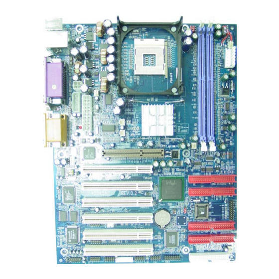
Page 6: 4D845Ap Motherboard Layout
Chapter 1 Chapter 1 Chapter 1 Chapter 1 Chapter 1 Motherboard Description Motherboard Description Motherboard Description Motherboard Description Motherboard Description 1.4 4D845AP Motherboard Layout 1 - 4 1 - 4 1 - 4 1 - 4 1 - 4... - Page 7 Chapter 1 Chapter 1 Chapter 1 Chapter 1 Chapter 1 Motherboard Description Motherboard Description Motherboard Description Motherboard Description Motherboard Description 1.4 4D845AP Layout T:Mouse B:KB T:LAN (Optional) B:USB1 Printer COM1 COM2 Intel Speak out JCLK Line in MIC in GAME1 AGP SLOT (Only 4X/1.5V Card)
- Page 8 Chapter 1 Chapter 1 Chapter 1 Chapter 1 Chapter 1 Motherboard Description Motherboard Description Motherboard Description Motherboard Description Motherboard Description 4. DDR SDRAM Sockets (DDR1/DDR2) 5. AGP Slot 6. Floppy Connector 7. IDE Connectors (IDE1/IDE2/ID3/ID4) 8. North Bridge (Intel 845E) 9.
-
Page 9: Cpu Installation
Chapter 1 Chapter 1 Chapter 1 Chapter 1 Chapter 1 Motherboard Description Motherboard Description Motherboard Description Motherboard Description Motherboard Description 1.5 CPU Installtion The motherboard operates with Socket 478 for Intel P4 processor. The CPU should always has a Heat Sink and cooling fan attached to prevent overheating. - Page 10 Chapter 1 Chapter 1 Chapter 1 Chapter 1 Chapter 1 Motherboard Description Motherboard Description Motherboard Description Motherboard Description Motherboard Description 1.6 DDR S D RAM Installtion The motherboard supports a maximized 2GB memory. It provides three 184-pin unbuffered DDR sockets. It supports 64MB to 1GB DDR memory module.
-
Page 11: Connectors & Jumper Setting
Chapter 1 Chapter 1 Chapter 1 Chapter 1 Chapter 1 Motherboard Description Motherboard Description Motherboard Description Motherboard Description Motherboard Description 1.7 Connectors & Jumpers S e tting 1.7.1 Back Panel I/O Connectors This motherboard provides the following back panel connectors: (Optional) MIDI/(GAME) Port Parallel (Printer) Port... -
Page 12: Serial Interface Ports
Chapter 1 Chapter 1 Chapter 1 Chapter 1 Chapter 1 Motherboard Description Motherboard Description Motherboard Description Motherboard Description Motherboard Description 1.7.1.3 Serial Interface Ports: COM1/COM2 The serial interface port is sometimes refered to as an RS-232 port or an asynchronous communication port. Mice, printers, modems and other peripheral devices can be connected to a serial port. - Page 13 Chapter 1 Chapter 1 Chapter 1 Chapter 1 Chapter 1 Motherboard Description Motherboard Description Motherboard Description Motherboard Description Motherboard Description Pin CN11Signal Pin CN11Signal +12V PinCN12 Signal PinCN12 Signal +12V +12V PinCN13 Signal PinCN13 Signal 3.3V 3.3V 3.3V -12V PS-ON PW-OK 5V_SB PinCN14 Signal...
-
Page 14: Floppy Disk Connector: Fdc
Chapter 1 Chapter 1 Chapter 1 Chapter 1 Chapter 1 Motherboard Description Motherboard Description Motherboard Description Motherboard Description Motherboard Description 1.7.3 Floppy Disk Connector: FDC This connector supports the provided floppy drive ribbon cable. After connecting the single end to the board, connect the two plugs on the other end to the floppy drives. -
Page 15: Cd-Audio-In Connectors: Cdin1/Cdin2
Chapter 1 Chapter 1 Chapter 1 Chapter 1 Chapter 1 Motherboard Description Motherboard Description Motherboard Description Motherboard Description Motherboard Description These connectors support cooling fans of 1Amp or less. Orientate the fans so that the heatsink fins allow airflow to go across the onboard heat sink(s) instead of the expansion slots. -
Page 16: Front Panel Connector: Panel
Chapter 1 Chapter 1 Chapter 1 Chapter 1 Chapter 1 Motherboard Description Motherboard Description Motherboard Description Motherboard Description Motherboard Description 1.7.7 Front USB Port Connector: USB2(SP-J8)/USB3 T:Mouse B:KB T:LAN (Optional) B:USB1 Printer COM1 USB2(SP-J8) COM2 Intel Speak out JCLK Line in MIC in GAME1 AGP SLOT... - Page 17 Chapter 1 Chapter 1 Chapter 1 Chapter 1 Chapter 1 Motherboard Description Motherboard Description Motherboard Description Motherboard Description Motherboard Description ATX Power Switch (PW_BN) The system power is controlled by a momentary switch connected to this lead. Pushing the button once will switch the system ON.
-
Page 18: Cmos Function Selection: Jbat
Chapter 1 Chapter 1 Chapter 1 Chapter 1 Chapter 1 Motherboard Description Motherboard Description Motherboard Description Motherboard Description Motherboard Description 1.7.9 CMOS Function Selection: JBAT A battery be used to retain the mainboard configuration in CMOS RAM. T:Mouse B:KB T:LAN (Optional) B:USB1 Printer... - Page 19 Chapter 1 Chapter 1 Chapter 1 Chapter 1 Chapter 1 Motherboard Description Motherboard Description Motherboard Description Motherboard Description Motherboard Description 1.7.10 CPU Clock Frequency Setting: JCLK Overclocking is operating a CPU/Processor beyond its specified frequency. JCLK jumper is used for the CPU Front Side Bus Frequencies from 100MHz to 133MHz.
-
Page 20: Ddr Ovp Select: J16
Chapter 1 Chapter 1 Chapter 1 Chapter 1 Chapter 1 Motherboard Description Motherboard Description Motherboard Description Motherboard Description Motherboard Description 1.7.11 Sound Center/Bass Selector: J4 T:Mouse B:KB T:LAN (Optional) B:USB1 Printer COM1 COM2 Intel Speak out JCLK Line in MIC in GAME1 AGP SLOT (Only 4X/1.5V Card) - Page 21 Chapter 1 Chapter 1 Chapter 1 Chapter 1 Chapter 1 Motherboard Description Motherboard Description Motherboard Description Motherboard Description Motherboard Description 1.7.14 Smart Panel Function: SP-J1/SP-J6/SP-J5/SP-J7 /SP-J8 (optional) T:Mouse B:KB T:LAN (Optional) B:USB1 Printer COM1 COM2 SP-J5 Intel Speak out JCLK Line in MIC in GAME1...
-
Page 22: Port 80 Debug Function:sp-J6
Chapter 1 Chapter 1 Chapter 1 Chapter 1 Chapter 1 Motherboard Description Motherboard Description Motherboard Description Motherboard Description Motherboard Description 1.7.14.1 Port 80 Debug Function: SP-J6 For Smart Panel connector(SP-J6) to M/B (SP-J6). Assignment Assignment Pin SP-J6 Pin SP-J6 ERD4 ERD0 ERD5 ERD1... -
Page 23: Front Com2 Connector:sp-J7
Chapter 1 Chapter 1 Chapter 1 Chapter 1 Chapter 1 Motherboard Description Motherboard Description Motherboard Description Motherboard Description Motherboard Description 1.7.14.4 Front COM2 Port Connector: SP-J7 For Smart Panel connector(SP-J7) to M/B (SP-J7). Assignment Assignment Pin SP-J7 Pin SP-J7 1.7.14.5 Front USB3,4 Port Connector: SP-J8 For Smart Panel connector(SP-J8) to M/B (SP-J8). -
Page 24: Bios Setup
Chapter 2 Chapter 2 BIOS Setup BIOS Setup Chapter 2 Chapter 2 Chapter 2 BIOS Setup BIOS Setup BIOS Setup Chapter Introduction This chapter discusses the Award Setup program built into the ROM BIOS. The Setup program allows the user to modify the basic system configuration. - Page 25 Chapter 2 Chapter 2 BIOS Setup BIOS Setup Chapter 2 Chapter 2 Chapter 2 BIOS Setup BIOS Setup BIOS Setup APM Support This AWARD BIOS supports Version 1.1&1.2 of the Advanced Power Management(APM) specification.Power management features are implemented via the System Management Interrupt(SMI).
- Page 26 Chapter 2 Chapter 2 BIOS Setup BIOS Setup Chapter 2 Chapter 2 Chapter 2 BIOS Setup BIOS Setup BIOS Setup Keystroke Function Up arrow Move to previous item Down arrow Move to next item Left arrow Move to the item on the left(menu bar) Right arrow Move to the item on the right(menu bar) Main Menu: Quit without saving changes...
-
Page 27: Main Menu
Chapter 2 Chapter 2 BIOS Setup BIOS Setup Chapter 2 Chapter 2 Chapter 2 BIOS Setup BIOS Setup BIOS Setup 2.1 Main Menu Once you enter AWARD BIOS CMOS Set up Utility, the Main Menu will appear on the screen. The Main Menu allows you to select from several setup function. - Page 28 Chapter 2 Chapter 2 BIOS Setup BIOS Setup Chapter 2 Chapter 2 Chapter 2 BIOS Setup BIOS Setup BIOS Setup Advanced BIOS Features This setup page includes all the items of the BIOS special enchanced features. Advanced Chipset Features This setup page includes all the items of the Chipset special enchanced features.
- Page 29 Chapter 2 Chapter 2 BIOS Setup BIOS Setup Chapter 2 Chapter 2 Chapter 2 BIOS Setup BIOS Setup BIOS Setup Load Optimized Defaults These settings are more likely to configure a workable computer when something is wrong. If you cannot boot the computer successfully, select the BIOS Setup options and try to diagnose the problem after the computer boots.
-
Page 30: Standard Cmos Features
Chapter 2 Chapter 2 BIOS Setup BIOS Setup Chapter 2 Chapter 2 Chapter 2 BIOS Setup BIOS Setup BIOS Setup 2.2 S t andard CMOS Features This item in the Standard CMOS Setup Menu is divided into 10 categories. Each category includes no, one or more than one setup items. - Page 31 Chapter 2 Chapter 2 BIOS Setup BIOS Setup Chapter 2 Chapter 2 Chapter 2 BIOS Setup BIOS Setup BIOS Setup Main Menu Selections This table shows the selections that you can make on the Main Menu. Item Options Description Date Month DD YYYY Set the system,date.
- Page 32 Chapter 2 Chapter 2 BIOS Setup BIOS Setup Chapter 2 Chapter 2 Chapter 2 BIOS Setup BIOS Setup BIOS Setup Item Options Description Halt On All Errors Select the situation in which you No Errors want the BIOS to stop the POST All, but Keyboard process and notify.
-
Page 33: Advanced Bios Features
Chapter 2 Chapter 2 BIOS Setup BIOS Setup Chapter 2 Chapter 2 Chapter 2 BIOS Setup BIOS Setup BIOS Setup 2.3 Advanced BIO S Features ¡·Figure 3. Advanced BIOS Features ¡· ¡· ¡· ¡· CMOS Setup Utility-Copyright (C) 1984-2001 Award Software Advanced BIOS Features Virus Warning Disabled... - Page 34 Chapter 2 Chapter 2 BIOS Setup BIOS Setup Chapter 2 Chapter 2 Chapter 2 BIOS Setup BIOS Setup BIOS Setup CPU L1 & L2 Cache This fields allow you to Enable or Disable the CPU’s “Level 1 & Level 2” cache. Caching allows better performance.
- Page 35 Chapter 2 Chapter 2 BIOS Setup BIOS Setup Chapter 2 Chapter 2 Chapter 2 BIOS Setup BIOS Setup BIOS Setup Boot Up NumLock Status Select power on state for Numlock. On (default) Numpad is number keys. Numpad is arrow keys. Gate A20 Option Select if chipset or keyboard controller should control Gate A20.
- Page 36 Chapter 2 Chapter 2 BIOS Setup BIOS Setup Chapter 2 Chapter 2 Chapter 2 BIOS Setup BIOS Setup BIOS Setup Setup (default) The system will boot, but access to Setup will be denied if the correct password is not entered in prompt. APIC Mode The Choices: Enabled(default), Disabled.
-
Page 37: Advanced Chipset Features
Chapter 2 Chapter 2 BIOS Setup BIOS Setup Chapter 2 Chapter 2 Chapter 2 BIOS Setup BIOS Setup BIOS Setup 2.4 Advanced Chipset Features This section allows you to configure the system based on the specific features of the installed chipset. This chipset manages bus speeds and access to system memory resources, such as DRAM and external cache. - Page 38 Chapter 2 Chapter 2 BIOS Setup BIOS Setup Chapter 2 Chapter 2 Chapter 2 BIOS Setup BIOS Setup BIOS Setup DRAM Latency Time 1.5 (default) Set DRAM latency Time to 1.5. Set DRAM latency Time to 2. Set DRAM latency Time to 2.5.
- Page 39 Chapter 2 Chapter 2 BIOS Setup BIOS Setup Chapter 2 Chapter 2 Chapter 2 BIOS Setup BIOS Setup BIOS Setup CMOS Setup Utility-Copyright(C) 1984-2001 Award Software Buffer Strength Control CMD Strength Control Auto Item Help DQ/DQS Strength Control Auto CKE X16 Strength Control Auto Menu Level CKE X8 Strength Control...
- Page 40 Chapter 2 Chapter 2 BIOS Setup BIOS Setup Chapter 2 Chapter 2 Chapter 2 BIOS Setup BIOS Setup BIOS Setup Memory Hole At 15-16M In order to improve performace, certain space in memory can be reserved for ISA cards. This memory must be mapped into the memory's space below 16MB.
-
Page 41: Integrated Peripherals
Chapter 2 Chapter 2 BIOS Setup BIOS Setup Chapter 2 Chapter 2 Chapter 2 BIOS Setup BIOS Setup BIOS Setup 2.5 Integrated Peripherals ¡·Figure 5. Integrated Peripherals ¡· ¡· ¡· ¡· CMOS Setup Utility-Copyright (C) 1984-2001 Award Software Integrated Peripherals On-Chip Primary PCI IDE Enabled Item Help... - Page 42 Chapter 2 Chapter 2 BIOS Setup BIOS Setup Chapter 2 Chapter 2 Chapter 2 BIOS Setup BIOS Setup BIOS Setup IDE Primary Master PIO(for onboard IDE 1st channel) Auto (default) BIOS will automatically detect the IDE HDD Accessing mode. Mode 0~4 Manually set the IDE Accessing mode.
- Page 43 Chapter 2 Chapter 2 BIOS Setup BIOS Setup Chapter 2 Chapter 2 Chapter 2 BIOS Setup BIOS Setup BIOS Setup IDE Secondary Master UDMA Auto (default) BIOS will automatically detect the IDE HDD Accessing mode. Disabled Disabled. IDE Secondary Slave UDMA Auto (default) BIOS will automatically detect the IDE HDD Accessing mode.
- Page 44 Chapter 2 Chapter 2 BIOS Setup BIOS Setup Chapter 2 Chapter 2 Chapter 2 BIOS Setup BIOS Setup BIOS Setup Power On Function Password Enter from 1 to 7 characters to set the Keyboard Power On Password. Hot Key Hot Key. Mouse Left Mouse Left.
- Page 45 Chapter 2 Chapter 2 BIOS Setup BIOS Setup Chapter 2 Chapter 2 Chapter 2 BIOS Setup BIOS Setup BIOS Setup Onboard Serial Port1 Select an address and corresponding interrupt for the first and second serial ports. The Choices: 3F8/IRQ4(default), Auto, (2F8/IRQ3), (3E8/IRQ4), (2E8/IRQ3), Disabled.
- Page 46 Chapter 2 Chapter 2 BIOS Setup BIOS Setup Chapter 2 Chapter 2 Chapter 2 BIOS Setup BIOS Setup BIOS Setup ECP/EPP Using Parallel port as ECP/EPP mode. PWRON After PWR-Fail This option will determine how the system will power on after a power failure.
-
Page 47: Power Management Setup
Chapter 2 Chapter 2 BIOS Setup BIOS Setup Chapter 2 Chapter 2 Chapter 2 BIOS Setup BIOS Setup BIOS Setup 2.6 Power Management S e tup The Power Management Setup allows you to configure your system to most effectively save energy while operating in a manner consistent with your own style of computer use. - Page 48 Chapter 2 Chapter 2 BIOS Setup BIOS Setup Chapter 2 Chapter 2 Chapter 2 BIOS Setup BIOS Setup BIOS Setup ACPI Suspend Type The item allows you to select the suspend type under ACPI operating system. S1(POS) (default) Power on Suspend. S3(STR) Suspend to RAM.
- Page 49 Chapter 2 Chapter 2 BIOS Setup BIOS Setup Chapter 2 Chapter 2 Chapter 2 BIOS Setup BIOS Setup BIOS Setup Suspend Type Stop Grant (default) Set Susped type is stop grant. PwrOn Suspend Set Suspend type is Power on Suspend. Modem Use IRQ This determines the IRQ, which can be applied in Modem use.
- Page 50 Chapter 2 Chapter 2 BIOS Setup BIOS Setup Chapter 2 Chapter 2 Chapter 2 BIOS Setup BIOS Setup BIOS Setup Power On By Ring Enabled Enabled. Disabled (default) Disabled. Resume by Alarm Disabled (default) Disabled. Enabled Enabled. Primary IDE 0/1 Disabled (default) Disabled.
-
Page 51: Pnp/Pci Configurations
Chapter 2 Chapter 2 BIOS Setup BIOS Setup Chapter 2 Chapter 2 Chapter 2 BIOS Setup BIOS Setup BIOS Setup 2.7 PnP/PCI Configurations This section describes configuring the PCI bus system. PCI or Personal Computer Interconnect,is a system which allows I/O devices to operate at speeds nearing the speed of the CPU itself when communicating with its own special components. - Page 52 Chapter 2 Chapter 2 BIOS Setup BIOS Setup Chapter 2 Chapter 2 Chapter 2 BIOS Setup BIOS Setup BIOS Setup Disabled (Default) is chosen, the system’s ESCD will update only when the new configuration varies from the last one. If Enabled is chosen, the system is forced to update ESCDs and then is automatically set to the “Disabled”...
- Page 53 Chapter 2 Chapter 2 BIOS Setup BIOS Setup Chapter 2 Chapter 2 Chapter 2 BIOS Setup BIOS Setup BIOS Setup PCI / VGA Palette Snoop Choose Disabled or Enabled. Some graphic controllers which are not VGA compatible take the output from a VGA controller and map it to their display as a way to provide boot information and VGA compatibility.
-
Page 54: Pc Health Status
Chapter 2 Chapter 2 BIOS Setup BIOS Setup Chapter 2 Chapter 2 Chapter 2 BIOS Setup BIOS Setup BIOS Setup 2.8 PC Health S t atus ¡·Figure 8. PC Health Status ¡· ¡· ¡· ¡· CMOS Setup Utility-Copyright (C) 1984-2001 Award Software PC Health Status Current System Temp Item Help... -
Page 55: Frequency/Voltage Control
Chapter 2 Chapter 2 BIOS Setup BIOS Setup Chapter 2 Chapter 2 Chapter 2 BIOS Setup BIOS Setup BIOS Setup 2.9 Fre q u ency / Voltage Control ¡·Figure 9. Frequency / Voltage Control ¡· ¡· ¡· ¡· CMOS Setup Utility-Copyright (C) 1984-2001 Award Software Frequency / Voltage Control CPU Clock Ratio Item Help... -
Page 56: Load Fail-Safe Defaults
Chapter 2 Chapter 2 BIOS Setup BIOS Setup Chapter 2 Chapter 2 Chapter 2 BIOS Setup BIOS Setup BIOS Setup AGP Voltage Select This option is support AGP vcore select. The Choices: +1.5V, +1.6V, +1.7V. DRAM Voltage Select This option is support DRAM vcore select. The Choices: +2.5V, +2.6V, +2.7V. -
Page 57: Load Optimized Defaults
Chapter 2 Chapter 2 BIOS Setup BIOS Setup Chapter 2 Chapter 2 Chapter 2 BIOS Setup BIOS Setup BIOS Setup 2.11 Load Optimized Defaults When you press <Enter> on this item, you get a confirmation dialog box with a message similar to: ¡·Figure 11. -
Page 58: Set Supervisor/User Password
Chapter 2 Chapter 2 BIOS Setup BIOS Setup Chapter 2 Chapter 2 Chapter 2 BIOS Setup BIOS Setup BIOS Setup 2.12 S e t S u pervisor / User Password ¡·Figure 12. Set Supervisor / User Password ¡· ¡· ¡· ¡·... -
Page 59: Save & Exit Setup
Chapter 2 Chapter 2 BIOS Setup BIOS Setup Chapter 2 Chapter 2 Chapter 2 BIOS Setup BIOS Setup BIOS Setup Password Disabled If you select “System” at the Security Option of BIOS Features Setup Menu, you will be prompted for the password every time when the system is rebooted, or any time when you try to enter Setup. -
Page 60: Exit Without Saving
Chapter 2 Chapter 2 BIOS Setup BIOS Setup Chapter 2 Chapter 2 Chapter 2 BIOS Setup BIOS Setup BIOS Setup 2.14 Exit Without S a ving ¡·Figure 14. Exit Without Saving ¡· ¡· ¡· ¡· CMOS Setup Utility-Copyright (C) 1984-2001 Award Software Standard CMOS Features Frequency/Voltage Control Advanced BIOS Features... -
Page 61: Driver Installation
Chapter There are motherboard drivers and utilities included in ACORP Bonus CD disc. You don't need to install all of them in order to boot your system. But after you finish the hardware installation, you have to install your operation system first (such as windows 98) before you can install any drivers or utilities. -
Page 62: Installing Intelinf Driver
Chapter 3 Chapter 3 Chapter 3 Chapter 3 Chapter 3 Driver Installation Driver Installation Driver Installation Driver Installation Driver Installation Chapter 3 Chapter 3 Driver Installation Driver Installation Chapter 3 Chapter 3 Chapter 3 Driver Installation Driver Installation Driver Installation 3.2 Installing Intelinf Driver This item install the Intel Chipset Software installation Utility that enables Plug-n-Play INF support for Intel chipset... - Page 63 Chapter 3 Chapter 3 Chapter 3 Chapter 3 Chapter 3 Driver Installation Driver Installation Driver Installation Driver Installation Driver Installation Chapter 3 Chapter 3 Driver Installation Driver Installation Chapter 3 Chapter 3 Chapter 3 Driver Installation Driver Installation Driver Installation Click "Finish".
- Page 64 Chapter 3 Chapter 3 Chapter 3 Chapter 3 Chapter 3 Driver Installation Driver Installation Driver Installation Driver Installation Driver Installation Chapter 3 Chapter 3 Driver Installation Driver Installation Chapter 3 Chapter 3 Chapter 3 Driver Installation Driver Installation Driver Installation Click "OK".
-
Page 65: Installing Audio Driver
Chapter 3 Chapter 3 Chapter 3 Chapter 3 Chapter 3 Driver Installation Driver Installation Driver Installation Driver Installation Driver Installation Chapter 3 Chapter 3 Driver Installation Driver Installation Chapter 3 Chapter 3 Chapter 3 Driver Installation Driver Installation Driver Installation 3.4.2 Connector Settings and Functions 3.4 Installing Audio Driver Headphone/... -
Page 66: Installing Lan Driver
Chapter 3 Chapter 3 Chapter 3 Chapter 3 Chapter 3 Driver Installation Driver Installation Driver Installation Driver Installation Driver Installation Chapter 3 Chapter 3 Driver Installation Driver Installation Chapter 3 Chapter 3 Chapter 3 Driver Installation Driver Installation Driver Installation 3.5 Installing LAN Driver (Optional) When your mainboard comes with the Realtek®... - Page 67 Chapter 3 Chapter 3 Chapter 3 Chapter 3 Chapter 3 Driver Installation Driver Installation Driver Installation Driver Installation Driver Installation Chapter 3 Chapter 3 Driver Installation Driver Installation Chapter 3 Chapter 3 Chapter 3 Driver Installation Driver Installation Driver Installation Select Selection your system "Driver"...
-
Page 68: Installing Raid Driver
Chapter 3 Chapter 3 Chapter 3 Chapter 3 Chapter 3 Driver Installation Driver Installation Driver Installation Driver Installation Driver Installation Chapter 3 Chapter 3 Driver Installation Driver Installation Chapter 3 Chapter 3 Chapter 3 Driver Installation Driver Installation Driver Installation Optimize Array For 3.6 Installing RAID Driver (Optional) Select which you want, performance (RAID 0) or security... - Page 69 Chapter 3 Chapter 3 Chapter 3 Chapter 3 Chapter 3 Driver Installation Driver Installation Driver Installation Driver Installation Driver Installation Chapter 3 Chapter 3 Driver Installation Driver Installation Chapter 3 Chapter 3 Chapter 3 Driver Installation Driver Installation Driver Installation 7.
- Page 70 Chapter 3 Chapter 3 Chapter 3 Chapter 3 Chapter 3 Driver Installation Driver Installation Driver Installation Driver Installation Driver Installation Chapter 3 Chapter 3 Driver Installation Driver Installation Chapter 3 Chapter 3 Chapter 3 Driver Installation Driver Installation Driver Installation 14.
- Page 71 Chapter 3 Chapter 3 Chapter 3 Chapter 3 Chapter 3 Driver Installation Driver Installation Driver Installation Driver Installation Driver Installation 17. Selecting "Win2000 Promise... " then go back to install Win2000 continuously. 3-20 3-20 3-20 3-20 3-20...
- Page 73 4D845AP System Compatibility Test Report 4D845AP System Compatibility Test Report Win2000 1024 x 768 x 32 bit CPU TYPE MEMORY TYPE AGP Model Vendor AGP Mode Dirver 3D MARK 2001 Quake III Demo 001 Nucleus Model Module IC_Vender & IC_NO...
- Page 74 4D845AP System Compatibility Test Report Device Model Vendor Model O.S. Driver Version Result Sound Card Creative Sound Blaster PC128 WIN98SE 4.12.01.2003 PASS YAMAHA YMF754-R WINXP 5.1.2501.0 PASS Creative Blaster live 5.1 WIN98SE 4.12.01.0905 PASS ESS SOLO-1 1989S WINXP 5.1.2526.0 PASS...
Need help?
Do you have a question about the 4D845AP and is the answer not in the manual?
Questions and answers