Table of Contents
Advertisement
Quick Links
4PX266A
User's Manual Version 1.0
The information presented in this publication has been
made carefully for reliability; however, no responsibility
is assumed for inaccuracies. Specifications are subject
to change without notice.
IBM, PC/AT, and PC/XT are trademarks of
International Business Machines Corporation.
Socket478 is a trademark of Intel Corporation
AWARD is a registered trademark of Phoenix
Sofftware Inc.
MS-DOS and WINDOWS NT are registered
trademarks of Microsoft Corporation.
Trademarks and/or registered trademarks are the
properties of their respective owners.
i
Advertisement
Table of Contents

Related Manuals for Acorp 4PX266A


Summary of Contents for Acorp 4PX266A
- Page 1 4PX266A User's Manual Version 1.0 The information presented in this publication has been made carefully for reliability; however, no responsibility is assumed for inaccuracies. Specifications are subject to change without notice. IBM, PC/AT, and PC/XT are trademarks of International Business Machines Corporation.
- Page 2 Table of Contents Intrnctctinn Intrnctctinn Intrnctctinn Intrnctctinn Intrnctctinn 1. Mnthdranarc Ddrcriotinn 1. Mnthdranarc Ddrcriotinn 1. Mnthdranarc Ddrcriotinn 1. Mnthdranarc Ddrcriotinn 1. Mnthdranarc Ddrcriotinn 1.1 Fdattrdr 1.1.1 Harcward 1.1.1 Snetward 1.1.3 Attachmdntr 1.1 Mnthdranarc Inrtallatinn 1.1.1 Mnthdranarc Mao 1.1.1 Mnthdranarc Layntt 1.3 Mnthdranarc Cnnndctnrr 1.3.1 Frnnt Pandl Cnnndctnr(PANEL( 1.3.1 Flnooy Dirk Cnnndctnr(FDD(...
- Page 3 Table of Contents 1.9 Atcin Staryrtdm 1.9.1 CD-Atcin-IN Cnnndctnr(CDIN1.CDIN1( 1-11 1.9.1 Tdldohnnd in Cnnndctnr(TAD( 1-11 1.1/ Smart Pandl Nnanarc Cnnndctnr 1.1/.1 Pnrt 8/ Ddatg Ftnctinn(SP-J6( 1-13 1.1/.1 Sdcnnc BINS Cnnndctnr(SP-J1( 1-13 1.1/.3 ATX LINE Cnnndctnr(SP-J5( 1-13 1.1/.4 Frnnt CNM1 Hdacdr Cnnndctnr(SP-J6( 1-14 1.1/.5 Frnnt TSB3,4 Hdacdr Cnnndctnr(SP-J8( 1-14...
- Page 4 Chaosdr 1 Chaosdr 1 Mnshdranarc Cdrbrhoshnn Mnshdranarc Cdrbrhoshnn Chaosdr 1 Chaosdr 1 Chaosdr 1 Mnshdranarc Cdrbrhoshnn Mnshdranarc Cdrbrhoshnn Mnshdranarc Cdrbrhoshnn Introduction System Overview This manual was written to help you start using this product as quickly and smoothly as possbile. Inside, you will find the answers to solve most of the problems.
- Page 5 Chaosdr 1 Chaosdr 1 Mnshdranarc Cdrbrhoshnn Mnshdranarc Cdrbrhoshnn Chaosdr 1 Chaosdr 1 Chaosdr 1 Mnshdranarc Cdrbrhoshnn Mnshdranarc Cdrbrhoshnn Mnshdranarc Cdrbrhoshnn 1.Motherboard Description 1.1 Features 1.1.1 Hardware -400MHz System Interface speed. -Single Socket 478 for Intel P4 up to 2GHz or higher(Northwood Processor).
-
Page 6: Smart Panel
Chaosdr 1 Chaosdr 1 Mnshdranarc Cdrbrhoshnn Mnshdranarc Cdrbrhoshnn Chaosdr 1 Chaosdr 1 Chaosdr 1 Mnshdranarc Cdrbrhoshnn Mnshdranarc Cdrbrhoshnn Mnshdranarc Cdrbrhoshnn Hardware Monitor Function -CPU Fan Speed Monitor. -CPU Temperature Monitor. -System Voltage Monitor. Flash Memory -Support 2MB flash memory. -Support ESCD Function. IDE Built-in On Board -Supports four IDE devices. - Page 7 Chaosdr 1 Chaosdr 1 Mnshdranarc Cdrbrhoshnn Mnshdranarc Cdrbrhoshnn Chaosdr 1 Chaosdr 1 Chaosdr 1 Mnshdranarc Cdrbrhoshnn Mnshdranarc Cdrbrhoshnn Mnshdranarc Cdrbrhoshnn I/O Built-in On Board -Supports one multi-mode Parallel Port. (1)Standard & Bidirection Parallel Port (2)Enhanced Parallel Port (EPP) (3)Extended Capabilities Port -Supports two serial ports, 16550 UART.
-
Page 8: Motherboard Installation
Chaosdr 1 Chaosdr 1 Mnshdranarc Cdrbrhoshnn Mnshdranarc Cdrbrhoshnn Chaosdr 1 Chaosdr 1 Chaosdr 1 Mnshdranarc Cdrbrhoshnn Mnshdranarc Cdrbrhoshnn Mnshdranarc Cdrbrhoshnn 1.2 Motherboard Installation 1.2.1 Motherboard Map 1 - 5 1 - 5 1 - 5 1 - 5 1 - 5... -
Page 9: Motherboard Layout
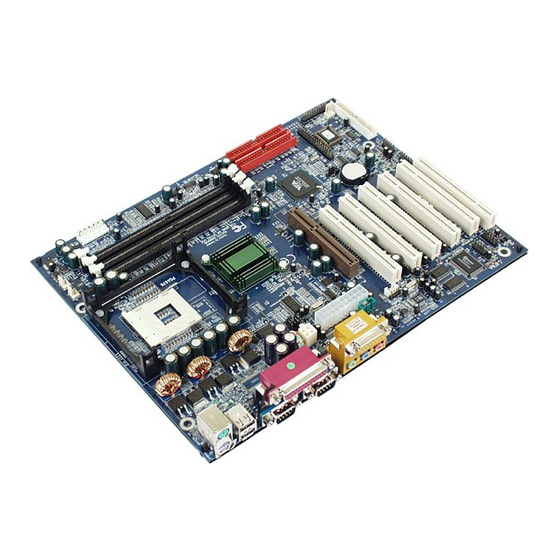
Chaosdr 1 Chaosdr 1 Mnshdranarc Cdrbrhoshnn Mnshdranarc Cdrbrhoshnn Chaosdr 1 Chaosdr 1 Chaosdr 1 Mnshdranarc Cdrbrhoshnn Mnshdranarc Cdrbrhoshnn Mnshdranarc Cdrbrhoshnn 1.2.2 Motherboard Layout FAN1 FAN3 T:LAN B:USB1 COM1 Printer COM2 Speak out GAME1 Line in MIC in AGP SLOT PCI1 PCI2 JBAT PCI3... -
Page 10: Motherboard Connectors
Chaosdr 1 Chaosdr 1 Mnshdranarc Cdrbrhoshnn Mnshdranarc Cdrbrhoshnn Chaosdr 1 Chaosdr 1 Chaosdr 1 Mnshdranarc Cdrbrhoshnn Mnshdranarc Cdrbrhoshnn Mnshdranarc Cdrbrhoshnn 1.3 Motherboard Connectors FAN1 FAN3 T:LAN B:USB1 COM1 Printer COM2 Speak out GAME1 Line in MIC in AGP SLOT PCI1 PCI2 JBAT PCI3... -
Page 11: Speaker Connector (Speaker)
Chaosdr 1 Chaosdr 1 Mnshdranarc Cdrbrhoshnn Mnshdranarc Cdrbrhoshnn Chaosdr 1 Chaosdr 1 Chaosdr 1 Mnshdranarc Cdrbrhoshnn Mnshdranarc Cdrbrhoshnn Mnshdranarc Cdrbrhoshnn 1.3.1 Front Panel Connector (PANEL) PANEL Connector SPEAKER HD_LED RESET PW_BN EXTSMI S3_LED PW_LED ATX Power Switch (PW_BN) The system power is controlled by a momentary switch connected to this lead. -
Page 12: Floppy Disk Connector (Fdd)
Chaosdr 1 Chaosdr 1 Mnshdranarc Cdrbrhoshnn Mnshdranarc Cdrbrhoshnn Chaosdr 1 Chaosdr 1 Chaosdr 1 Mnshdranarc Cdrbrhoshnn Mnshdranarc Cdrbrhoshnn Mnshdranarc Cdrbrhoshnn SMI Suspend Switch Lead (EXTSMI) This allows the user to manually place the system into a suspend mode of Green mode. System activity will be instantly decreased to save electricity and expand the life of certain components when the system is not in use. - Page 13 Chaosdr 1 Chaosdr 1 Mnshdranarc Cdrbrhoshnn Mnshdranarc Cdrbrhoshnn Chaosdr 1 Chaosdr 1 Chaosdr 1 Mnshdranarc Cdrbrhoshnn Mnshdranarc Cdrbrhoshnn Mnshdranarc Cdrbrhoshnn 1.3.4 ATX 4-pin/ATX 20-pin/AUX 6-pin Power Connector (CN3/ATX/AUX) -This connector supports the power button on-board. Using the ATX power supply, functions such as Modem Ring Wake- Up and Soft Power Off are supported on this motherboard .
-
Page 14: Back Panel Connectors
Chaosdr 1 Chaosdr 1 Mnshdranarc Cdrbrhoshnn Mnshdranarc Cdrbrhoshnn Chaosdr 1 Chaosdr 1 Chaosdr 1 Mnshdranarc Cdrbrhoshnn Mnshdranarc Cdrbrhoshnn Mnshdranarc Cdrbrhoshnn 1.4 Back Panel Connectors MIDI/(GAME) Port Parallel (Printer) Port RJ-45 (15-pin Female) (25-pin Female) PS/2 Mouse PS/2 Keyboard USB1 COM2 SPEAKER COM1 (6-pin Female) - Page 15 Chaosdr 1 Chaosdr 1 Mnshdranarc Cdrbrhoshnn Mnshdranarc Cdrbrhoshnn Chaosdr 1 Chaosdr 1 Chaosdr 1 Mnshdranarc Cdrbrhoshnn Mnshdranarc Cdrbrhoshnn Mnshdranarc Cdrbrhoshnn Front Two USB Connectors: USB2 & USB3 FAN1 FAN3 T:LAN B:USB1 COM1 Printer COM2 Speak out GAME1 Line in MIC in AGP SLOT PCI1 PCI2...
-
Page 16: Serial And Parallel Interface Ports
Chaosdr 1 Chaosdr 1 Mnshdranarc Cdrbrhoshnn Mnshdranarc Cdrbrhoshnn Chaosdr 1 Chaosdr 1 Chaosdr 1 Mnshdranarc Cdrbrhoshnn Mnshdranarc Cdrbrhoshnn Mnshdranarc Cdrbrhoshnn 1.5 Serial and Parallel Interface Ports This system comes equipped with two serial ports and one parallel port. Both types of interface ports will be explained in this chapter. -
Page 17: Parallel Interface Port
Chaosdr 1 Chaosdr 1 Mnshdranarc Cdrbrhoshnn Mnshdranarc Cdrbrhoshnn Chaosdr 1 Chaosdr 1 Chaosdr 1 Mnshdranarc Cdrbrhoshnn Mnshdranarc Cdrbrhoshnn Mnshdranarc Cdrbrhoshnn FAN1 FAN3 T:LAN B:USB1 COM1 Printer COM2 Speak out GAME1 Line in MIC in AGP SLOT PCI1 PCI2 JBAT PCI3 SP-J2 I/O CHIP PCI4... -
Page 18: Cpu Installation Procedure: Socket 478
Chaosdr 1 Chaosdr 1 Mnshdranarc Cdrbrhoshnn Mnshdranarc Cdrbrhoshnn Chaosdr 1 Chaosdr 1 Chaosdr 1 Mnshdranarc Cdrbrhoshnn Mnshdranarc Cdrbrhoshnn Mnshdranarc Cdrbrhoshnn 1.6 CPU Installation 1.6.1 CPU Installation Procedure: Socket 478 1. Pull the lever sideways away from the socket then raise the lever to a 90-degree angle. - Page 19 Chaosdr 1 Chaosdr 1 Mnshdranarc Cdrbrhoshnn Mnshdranarc Cdrbrhoshnn Chaosdr 1 Chaosdr 1 Chaosdr 1 Mnshdranarc Cdrbrhoshnn Mnshdranarc Cdrbrhoshnn Mnshdranarc Cdrbrhoshnn 1.6.2 CPU Clock Frequency Setting: J4 Overclocking is operating a CPU/Processor beyond its specified frequency. J4 jumper is used for the CPU Front Side Bus Frequencies from 66MHz to 133MHz.
-
Page 20: Jumper Setting
Chaosdr 1 Chaosdr 1 Mnshdranarc Cdrbrhoshnn Mnshdranarc Cdrbrhoshnn Chaosdr 1 Chaosdr 1 Chaosdr 1 Mnshdranarc Cdrbrhoshnn Mnshdranarc Cdrbrhoshnn Mnshdranarc Cdrbrhoshnn 1.7 Jumper Setting A jumper has two or more pins that can be covered by a plastic jumper cap, allowing you to select different system FAN1 options. -
Page 21: Pin Assignment
Chaosdr 1 Chaosdr 1 Mnshdranarc Cdrbrhoshnn Mnshdranarc Cdrbrhoshnn Chaosdr 1 Chaosdr 1 Chaosdr 1 Mnshdranarc Cdrbrhoshnn Mnshdranarc Cdrbrhoshnn Mnshdranarc Cdrbrhoshnn 1.7.1 CPU/System Fan Connector: Fan2 Assignment FAN2 +12VDC Ground 1.7.1 CPU/System Fan Connector: Fan3 Assignment +12VDC Ground 1.7.2 Wake-On Modem Header: WOM Assignment 5V_SB Ground... -
Page 22: Irda Connector: Ir
Chaosdr 1 Chaosdr 1 Mnshdranarc Cdrbrhoshnn Mnshdranarc Cdrbrhoshnn Chaosdr 1 Chaosdr 1 Chaosdr 1 Mnshdranarc Cdrbrhoshnn Mnshdranarc Cdrbrhoshnn Mnshdranarc Cdrbrhoshnn 1.7.5 CMOS Function Selection: JBAT Assignment Normal (Default) Clear CMOS NOTE: (Please follow the procedure below to clear CMOS data.) (1)Remove the AC power line. -
Page 23: Ddr Sdram Installation
Chaosdr 1 Chaosdr 1 Mnshdranarc Cdrbrhoshnn Mnshdranarc Cdrbrhoshnn Chaosdr 1 Chaosdr 1 Chaosdr 1 Mnshdranarc Cdrbrhoshnn Mnshdranarc Cdrbrhoshnn Mnshdranarc Cdrbrhoshnn 1.8 DDR SDRAM Installation 1.8.1 DDR DDR SDRAM Access Time: 2.5V Unbuffered PC1600/ PC2100 Type required. DDR SDRAM Type: 64MB, 128MB, 256MB, 512MB, 1GB DDR Module. -
Page 24: Audio Subsystem
Chaosdr 1 Chaosdr 1 Mnshdranarc Cdrbrhoshnn Mnshdranarc Cdrbrhoshnn Chaosdr 1 Chaosdr 1 Chaosdr 1 Mnshdranarc Cdrbrhoshnn Mnshdranarc Cdrbrhoshnn Mnshdranarc Cdrbrhoshnn 1.9 Audio Subsystem FAN1 FAN3 T:LAN B:USB1 COM1 Printer COM2 Speak out GAME1 Line in MIC in AGP SLOT CDIN1 CDIN2 PCI1 PCI2... - Page 25 Chaosdr 1 Chaosdr 1 Mnshdranarc Cdrbrhoshnn Mnshdranarc Cdrbrhoshnn Chaosdr 1 Chaosdr 1 Chaosdr 1 Mnshdranarc Cdrbrhoshnn Mnshdranarc Cdrbrhoshnn Mnshdranarc Cdrbrhoshnn 1.9.2 Telephone in Connector: TAD Assignment Pin TAD PHONE MONO_OUT 1.10 Smart Panel Onboard Connector FAN1 FAN3 T:LAN B:USB1 COM1 Printer COM2 Speak out...
- Page 26 Chaosdr 1 Chaosdr 1 Mnshdranarc Cdrbrhoshnn Mnshdranarc Cdrbrhoshnn Chaosdr 1 Chaosdr 1 Chaosdr 1 Mnshdranarc Cdrbrhoshnn Mnshdranarc Cdrbrhoshnn Mnshdranarc Cdrbrhoshnn 1.10.1 Port 80 Debug Function: SP-J6 For Smart Panel connector(SP-J6) to M/B (SP-J6). Assignment Assignment Pin SP-J6 Pin SP-J6 ERD4 ERD0 ERD5 ERD1...
- Page 27 Chaosdr 1 Chaosdr 1 Mnshdranarc Cdrbrhoshnn Mnshdranarc Cdrbrhoshnn Chaosdr 1 Chaosdr 1 Chaosdr 1 Mnshdranarc Cdrbrhoshnn Mnshdranarc Cdrbrhoshnn Mnshdranarc Cdrbrhoshnn 1.10.4 Front COM2 Header Conn.: SP-J7(COM2) For Smart Panel connector(SP-J7) to M/B (SP-J7). Assignment Assignment Pin SP-J7 Pin SP-J7 1.10.5 Front USB3,4 Header Conn.: SP-J8(USB3) For Smart Panel connector(SP-J8) to M/B (USB3).
-
Page 28: Bios Setup
Bhapter 1 Bhapter 1 BIOS Settp BIOS Settp Bhapter 1 Bhapter 1 Bhapter 1 BIOS Settp BIOS Settp BIOS Settp 2. BIOS Setup Introduction This manual discussed the Award Setup program built into the ROM BIOS. The Setup program allows the user to modify the basic system configuration. -
Page 29: Apm Support
Bhapter 1 Bhapter 1 BIOS Settp BIOS Settp Bhapter 1 Bhapter 1 Bhapter 1 BIOS Settp BIOS Settp BIOS Settp APM Support This AWARD BIOS supports Version 1.1&1.2 of the Advanced Power Management(APM) specification.Power management features are implemented via the System Management Interrupt(SMI). - Page 30 Bhapter 1 Bhapter 1 BIOS Settp BIOS Settp Bhapter 1 Bhapter 1 Bhapter 1 BIOS Settp BIOS Settp BIOS Settp Keystroke Function Up arrow Move to previous item Down arrow Move to next item Left arrow Move to the item on the left(menu bar) Right arrow Move to the item on the right(menu bar) Main Menu: Quit without saving changes...
- Page 31 Bhapter 1 Bhapter 1 BIOS Settp BIOS Settp Bhapter 1 Bhapter 1 Bhapter 1 BIOS Settp BIOS Settp BIOS Settp 2.1 Main Menu Once you enter AWARD BIOS CMOS Setup Utility, the Main Menu will appear on the screen. The Main Menu allows you to select from several setup function.
-
Page 32: Integrated Peripherals
Bhapter 1 Bhapter 1 BIOS Settp BIOS Settp Bhapter 1 Bhapter 1 Bhapter 1 BIOS Settp BIOS Settp BIOS Settp Advanced BIOS Features This setup page includes all the items of the BIOS special enchanced features. Advanced Chipset Features This setup page includes all the items of the Chipset special enchanced features. -
Page 33: Load Optimized Defaults
Bhapter 1 Bhapter 1 BIOS Settp BIOS Settp Bhapter 1 Bhapter 1 Bhapter 1 BIOS Settp BIOS Settp BIOS Settp Load Optimized Defaults These settings are more likely to configure a workable computer when something is wrong. If you cannot boot the computer successfully, select the BIOS Setup options and try to diagnose the problem after the computer boots. -
Page 34: Standard Cmos Features
Bhapter 1 Bhapter 1 BIOS Settp BIOS Settp Bhapter 1 Bhapter 1 Bhapter 1 BIOS Settp BIOS Settp BIOS Settp 2.2 Standard CMOS Features This item in the Standard CMOS Setup Menu is divided into 10 categories. Each category includes no, one or more than one setup items. -
Page 35: Main Menu Selections
Bhapter 1 Bhapter 1 BIOS Settp BIOS Settp Bhapter 1 Bhapter 1 Bhapter 1 BIOS Settp BIOS Settp BIOS Settp Main Menu Selections This table shows the selections that you can make on the Main Menu. Item Options Description Date Month DD YYYY Set the system,date. -
Page 36: Ide Primary Master
Bhapter 1 Bhapter 1 BIOS Settp BIOS Settp Bhapter 1 Bhapter 1 Bhapter 1 BIOS Settp BIOS Settp BIOS Settp Item Options Description Halt On All Errors Select the situation in which you No Errors want the BIOS to stop the POST All, but Keyboard process and notify. -
Page 37: Advanced Bios Features
Bhapter 1 Bhapter 1 BIOS Settp BIOS Settp Bhapter 1 Bhapter 1 Bhapter 1 BIOS Settp BIOS Settp BIOS Settp 2.3 Advanced BIOS Features ◎ ◎ ◎ ◎ ◎ Figure 3. Advanced BIOS Features CMOS Setup Utility-Copyright (C) 1984-2001 Award Software Advanced BIOS Features Virus Warning Disabled... - Page 38 Bhapter 1 Bhapter 1 BIOS Settp BIOS Settp Bhapter 1 Bhapter 1 Bhapter 1 BIOS Settp BIOS Settp BIOS Settp CPU L2 Cache ECC Checking The item allows you to enable/disable CPU L2 Cache ECC Checking. The Choices: Enabled(default), Disabled. Quick Power On Self Test This category speeds up Power on Self-Test(POST) after you power up the computer.
-
Page 39: Security Option
Bhapter 1 Bhapter 1 BIOS Settp BIOS Settp Bhapter 1 Bhapter 1 Bhapter 1 BIOS Settp BIOS Settp BIOS Settp Typematic Rate Setting Enabled Enabled this option to adjust the keystroke repeat rate. Disabled (default) Disabled. Typematic Rate (Char/Sec) Range between 6(default) and 30 characters per second. This option controls the speed of repeating keystrokes. - Page 40 Bhapter 1 Bhapter 1 BIOS Settp BIOS Settp Bhapter 1 Bhapter 1 Bhapter 1 BIOS Settp BIOS Settp BIOS Settp C8000-CFFFF Shadow / D0000-DFFFF Shadow Determines whether video BIOS will be copied to RAM for faster execution. Enabled Optional ROM is Shadowed. Disabled (default) Optional ROM is not Shadowed.
-
Page 41: Advanced Chipset Features
Bhapter 1 Bhapter 1 BIOS Settp BIOS Settp Bhapter 1 Bhapter 1 Bhapter 1 BIOS Settp BIOS Settp BIOS Settp 2.4 Advanced Chipset Features This section allows you to configure the system based on the specific features of the installed chipset. This chipset manages bus speeds and access to system memory resources, such as DRAM and external cache. -
Page 42: Dram Clock
Bhapter 1 Bhapter 1 BIOS Settp BIOS Settp Bhapter 1 Bhapter 1 Bhapter 1 BIOS Settp BIOS Settp BIOS Settp DRAM Clock This item determines DRAM Clock following the CPU host clock. The Choices: By SPD(default), 100, 133. DRAM Timing The DRAM timing is controlled by the DRAM Timing Registers. -
Page 43: Agp Driving Control
Bhapter 1 Bhapter 1 BIOS Settp BIOS Settp Bhapter 1 Bhapter 1 Bhapter 1 BIOS Settp BIOS Settp BIOS Settp AGP Aperture Size Select the size of the Accelerated Graphic Port(AGP) aperture. The aperture is a portion of the PCI memory address range dedicated for graphics memory address space. -
Page 44: Cpu To Pci Write Buffer
Bhapter 1 Bhapter 1 BIOS Settp BIOS Settp Bhapter 1 Bhapter 1 Bhapter 1 BIOS Settp BIOS Settp BIOS Settp CMOS Setup Utility-Copyright (C) 1984-2001 Award Software CPU & PCI Bus Control CPU to PCI Write Buffer Enabled Item Help PCI Master 0 WS Write Enabled PCI Delay Transaction... -
Page 45: Memory Hole
Bhapter 1 Bhapter 1 BIOS Settp BIOS Settp Bhapter 1 Bhapter 1 Bhapter 1 BIOS Settp BIOS Settp BIOS Settp DRAM Driv-0 The Choices: Auto(default), Manual. DRAM Driv-1 The Choices: Auto(default), Manual. Memory Hole In order to improve performace, certain space in memory can be reserved for ISA cards. - Page 46 Bhapter 1 Bhapter 1 BIOS Settp BIOS Settp Bhapter 1 Bhapter 1 Bhapter 1 BIOS Settp BIOS Settp BIOS Settp 2.5 Integrated Peripherals ◎ ◎ ◎ ◎ ◎ Figure 5. Integrated Peripherals CMOS Setup Utility-Copyright (C) 1984-2001 Award Software Integrated Peripherals VIA Onchip IDE Device Press Enter Item Help...
- Page 47 Bhapter 1 Bhapter 1 BIOS Settp BIOS Settp Bhapter 1 Bhapter 1 Bhapter 1 BIOS Settp BIOS Settp BIOS Settp IDE Prefetch Mode The onboard IDE drive interface supports IDE prefetching, for faster drive access. If you install a primary and or secondary add-in IDE interface, set this field to Disabled if the interface does not support prefetching.
- Page 48 Bhapter 1 Bhapter 1 BIOS Settp BIOS Settp Bhapter 1 Bhapter 1 Bhapter 1 BIOS Settp BIOS Settp BIOS Settp Primary Slave UDMA Auto (default) BIOS will automatically detect the IDE HDD Accessing mode. Disabled Disabled. Secondary Master UDMA Auto (default) BIOS will automatically detect the IDE HDD Accessing mode.
-
Page 49: Onchip Lan Boot Rom
Bhapter 1 Bhapter 1 BIOS Settp BIOS Settp Bhapter 1 Bhapter 1 Bhapter 1 BIOS Settp BIOS Settp BIOS Settp OnChip LAN Boot ROM The Choices: Disabled(default), Enabled. CMOS Setup Utility-Copyright (C) 1984-2001 Award Software Super IO Device Onboard FDC Controller Enabled Item Help Onboard Serial Port 1... -
Page 50: Onboard Parallel Port
Bhapter 1 Bhapter 1 BIOS Settp BIOS Settp Bhapter 1 Bhapter 1 Bhapter 1 BIOS Settp BIOS Settp BIOS Settp 3E8/IRQ4 Enabled onboard Serial Port2 and address is 3E8. 2E8/IRQ3 Enabled onboard Serial Port2 and address is 2E8. Disabled Disabled. UART Mode Select This item allows you to select which Infra Red(IR) function of the onboard I/O chip you wish to use. -
Page 51: Init Display First
Bhapter 1 Bhapter 1 BIOS Settp BIOS Settp Bhapter 1 Bhapter 1 Bhapter 1 BIOS Settp BIOS Settp BIOS Settp Midi Port Address Set Midi Port address to 300. 330 (default) Set Midi Port address to 330. Midi Port IRQ 10 (default) Set Midi Port IRQ to 10. -
Page 52: Power Management Setup
Bhapter 1 Bhapter 1 BIOS Settp BIOS Settp Bhapter 1 Bhapter 1 Bhapter 1 BIOS Settp BIOS Settp BIOS Settp 2.6 Power Management Setup The Power Management Setup allows you to configure your system to most effectively save energy while operating in a manner consistent with your own style of computer use. -
Page 53: Hdd Power Down
Bhapter 1 Bhapter 1 BIOS Settp BIOS Settp Bhapter 1 Bhapter 1 Bhapter 1 BIOS Settp BIOS Settp BIOS Settp HDD Power Down By default, this is “Disabled”, meaning that no matter the mode of the rest of the system, the hard drive will remain ready. -
Page 54: Modem Use Irq
Bhapter 1 Bhapter 1 BIOS Settp BIOS Settp Bhapter 1 Bhapter 1 Bhapter 1 BIOS Settp BIOS Settp BIOS Settp Modem Use IRQ This determines the IRQ, which can be applied in Modem use. 3(default) 4/5/7/9/10/11/NA Soft-Off by PWRBTN Pressing the power button for more than 4 seconds forces the system to enter the Soft-Off state when the system has “hung”. -
Page 55: Pci Master
Bhapter 1 Bhapter 1 BIOS Settp BIOS Settp Bhapter 1 Bhapter 1 Bhapter 1 BIOS Settp BIOS Settp BIOS Settp LPT & COM When set to On, any event occurring at a COM(serial) / LPT (printer) port will awaken a system which has been powered down. -
Page 56: Irqs Activity Monitoring
Bhapter 1 Bhapter 1 BIOS Settp BIOS Settp Bhapter 1 Bhapter 1 Bhapter 1 BIOS Settp BIOS Settp BIOS Settp IRQs Activity Monitoring When set to On(default), any event occurring at Primary INTR will awaken a system which has been powered down. -
Page 57: Pnp Os Installed
Bhapter 1 Bhapter 1 BIOS Settp BIOS Settp Bhapter 1 Bhapter 1 Bhapter 1 BIOS Settp BIOS Settp BIOS Settp 2.7 PnP/PCI Configurations This section describes configuring the PCI bus system. PCI or Personal Computer Interconnect,is a system which allows I/O devices to operate at speeds nearing the speed of the CPU itself uses when communicating with its own special components. - Page 58 Bhapter 1 Bhapter 1 BIOS Settp BIOS Settp Bhapter 1 Bhapter 1 Bhapter 1 BIOS Settp BIOS Settp BIOS Settp Reset Configuration Data The system BIOS supports the PnP feature so the system needs to record which resource is assigned and proceeds resources from conflict.
-
Page 59: Resources Controlled By
Bhapter 1 Bhapter 1 BIOS Settp BIOS Settp Bhapter 1 Bhapter 1 Bhapter 1 BIOS Settp BIOS Settp BIOS Settp The above settings will be shown on the screen only if “Manual” is chosen for the resources controlled by function. Legacy is the term which signifies that a resource is assigned to the ISA Bus and provides for non-PnP ISA add-on cards. -
Page 60: Assign Irq For Vga
Bhapter 1 Bhapter 1 BIOS Settp BIOS Settp Bhapter 1 Bhapter 1 Bhapter 1 BIOS Settp BIOS Settp BIOS Settp PCI / VGA Palette Snoop Choose Disabled or Enabled. Some graphic controllers which are not VGA compatible take the output from a VGA controller and map it to their display as a way to provide boot information and VGA compatibility. -
Page 61: Pc Health Status
Bhapter 1 Bhapter 1 BIOS Settp BIOS Settp Bhapter 1 Bhapter 1 Bhapter 1 BIOS Settp BIOS Settp BIOS Settp 2.8 PC Health Status ◎ ◎ ◎ ◎ ◎ Figure 8. PC Health Status CMOS Setup Utility-Copyright (C) 1984-2001 Award Software PC Health Status CPU Warning Temperature Disabled... - Page 62 Bhapter 1 Bhapter 1 BIOS Settp BIOS Settp Bhapter 1 Bhapter 1 Bhapter 1 BIOS Settp BIOS Settp BIOS Settp CPU Warning Temperature(℃ ℃ ℃ ℃ ℃ ) Disabled (default) Disabled. 50 ℃ ℃ ℃ ℃ ℃ / / / / / 122℉ ℉ ℉ ℉ ℉ Monitor CPU Temp.at 50℃/ 122℉.
-
Page 63: Frequency/Voltage Control
Bhapter 1 Bhapter 1 BIOS Settp BIOS Settp Bhapter 1 Bhapter 1 Bhapter 1 BIOS Settp BIOS Settp BIOS Settp 2.9 Frequency / Voltage Control ◎ ◎ ◎ ◎ ◎ Figure 9. Frequency / Voltage Control CMOS Setup Utility-Copyright (C) 1984-2001 Award Software Frequency / Voltage Control CPU Vcore Select Default... -
Page 64: Load Fail-Safe Defaults
Bhapter 1 Bhapter 1 BIOS Settp BIOS Settp Bhapter 1 Bhapter 1 Bhapter 1 BIOS Settp BIOS Settp BIOS Settp 2.10 Load Fail-Safe Defaults When you press <Enter> on this item, you get a confirmation dialog box with a message similar to: ◎... - Page 65 Bhapter 1 Bhapter 1 BIOS Settp BIOS Settp Bhapter 1 Bhapter 1 Bhapter 1 BIOS Settp BIOS Settp BIOS Settp 2.11 Load Optimized Defaults When you press <Enter> on this item, you get a confirmation dialog box with a message similar to: ◎...
-
Page 66: Set Supervisor/User Password
Bhapter 1 Bhapter 1 BIOS Settp BIOS Settp Bhapter 1 Bhapter 1 Bhapter 1 BIOS Settp BIOS Settp BIOS Settp 2.12 Set Supervisor / User Password ◎ ◎ ◎ ◎ ◎ Figure 12. Set Supervisor / User Password CMOS Setup Utility-Copyright (C) 1984-2001 Award Software Standard CMOS Features Frequency/Voltage Control Advanced BIOS Features... - Page 67 Bhapter 1 Bhapter 1 BIOS Settp BIOS Settp Bhapter 1 Bhapter 1 Bhapter 1 BIOS Settp BIOS Settp BIOS Settp Password Disabled If you select “System” at the Security Option of BIOS Features Setup Menu, you will be prompted for the password every time when the system is rebooted, or any time when you try to enter Setup.
-
Page 68: Save And Exit Setup
Bhapter 1 Bhapter 1 BIOS Settp BIOS Settp Bhapter 1 Bhapter 1 Bhapter 1 BIOS Settp BIOS Settp BIOS Settp 2.13 Save & Exit Setup ◎ ◎ ◎ ◎ ◎ Figure 13. Save & Exit Setup CMOS Setup Utility-Copyright (C) 1984-2001 Award Software Standard CMOS Features Frequency/Voltage Control Advanced BIOS Features... -
Page 69: Exit Without Saving
Bhapter 1 Bhapter 1 BIOS Settp BIOS Settp Bhapter 1 Bhapter 1 Bhapter 1 BIOS Settp BIOS Settp BIOS Settp 2.14 Exit Without Saving ◎ ◎ ◎ ◎ ◎ Figure 14. Exit Without Saving CMOS Setup Utility-Copyright (C) 1984-2001 Award Software Standard CMOS Features Frequency/Voltage Control Advanced BIOS Features... -
Page 70: Auto-Run Menu
Chaoser 3 Chaoser 3 Chaoser 3 Crhver Inrsallashnn Crhver Inrsallashnn Crhver Inrsallashnn Chaoser 3 Chaoser 3 Crhver Inrsallashnn Crhver Inrsallashnn 3. Driver Installation Introduction There are motherboard drivers in CD disc. You don't need to install all of them in order to boot your system. But after you finish thehardware installation, you have to install your operating system first (such as windows 98) before you can install any drivers or utilities. -
Page 71: Installing Via 4 In 1 Driver
Chaoser 3 Chaoser 3 Crhver Inrsallashnn Crhver Inrsallashnn Chaoser 3 Chaoser 3 Chaoser 3 Crhver Inrsallashnn Crhver Inrsallashnn Crhver Inrsallashnn 3.2 Installing VIA 4 in 1 Driver You can install the VIA 4 in 1 driver (IDE Bus master (For Windows NT use), VIA ATAPI Vendor Support Driver, VIA AGP, IRQ Routing Driver (For Windows 98 use), VIA Registry (INF) Driver) from the Bonus Pack CD disc auto-run menu. -
Page 72: Installing Audio Driver
Chaoser 3 Chaoser 3 Chaoser 3 Crhver Inrsallashnn Crhver Inrsallashnn Crhver Inrsallashnn Chaoser 3 Chaoser 3 Crhver Inrsallashnn Crhver Inrsallashnn 3.3 Installing Audio Driver This motherboard comes with an AC97 CODEC and the sound controller is in VIA South Bridge chipset. This item install the VIA Audio for Microsoft Windows 9X/98SE/ME/ NT4.0/2000/XP. -
Page 73: Installing Lan Driver
Chaoser 3 Chaoser 3 Crhver Inrsallashnn Crhver Inrsallashnn Chaoser 3 Chaoser 3 Chaoser 3 Crhver Inrsallashnn Crhver Inrsallashnn Crhver Inrsallashnn 3.4 Installing LAN Driver When your mainboard comes with the VIA PCI 10/100Mb Fast Ethernet Adapter, you must install the VIA® LAN driver to support the LAN function. - Page 74 Chaoser 3 Chaoser 3 Chaoser 3 Crhver Inrsallashnn Crhver Inrsallashnn Crhver Inrsallashnn Chaoser 3 Chaoser 3 Crhver Inrsallashnn Crhver Inrsallashnn Select "Driver" then Click "Update Driver" Item. Click "Next" Item. Click "Next" Item. 3 - 5 3 - 5 3 - 5 3 - 5 3 - 5...
- Page 75 Chaoser 3 Chaoser 3 Crhver Inrsallashnn Crhver Inrsallashnn Chaoser 3 Chaoser 3 Chaoser 3 Crhver Inrsallashnn Crhver Inrsallashnn Crhver Inrsallashnn Selection your system environment follow path : \MB\LAN_driver\VT6103 then Click "Next" Item. Click "Next" Item. Click "Finish" Item. 3 - 6 3 - 6 3 - 6 3 - 6...
- Page 76 4PX266A System Compatibility Test Report Note: This test report is for your reference, we would like to suggest you to use these devises that we had apporoved. A. CPU & Memory Compatibility Test Pass Pentium 4 Pentium 4 Pentium 4 MEMORY 1.5GHz...
- Page 77 4PX266A System Compatibility Test Report B. AGP Display Compatibility Test Win98 SE 1024 x 768 x 32 bit AGP Model Vendor AGP Mode Dirver 3D MARK 2001 Quake III Demo 001 Version Bench Mode frames seconds V7100 ASUS 4.13.01.1241 2227 1346 10.8...
- Page 78 4PX266A System Compatibility Test Report C. PCI/ISA Device Compatibility Test Device Model Vendor Model Driver Version Result LAN Card D_Link 2.52 PASS Intel PILA8460C3 5.40.17.0000 PASS Realtak 8319A 5.352.1215.1998 PASS Sound Card Creative Live 5.1 4.12.01.0905 PASS ESS Solo-1 1989S 4.12.01.7135...
- Page 79 4PX266A System Compatibility Test Report E. System Reliability Test O.S. Environment Test Software Version Loop times Result Win98 SE WinStone 99 Business Test 8 Hours PASS 3D MARK 2001 DEMO Mode Test 1. 0 8 Hours PASS Win ME Quake III DEMO Mode Test 1.
Need help?
Do you have a question about the 4PX266A and is the answer not in the manual?
Questions and answers