
Related Manuals for Biamp VA-8600


Summary of Contents for Biamp VA-8600
- Page 1 ® Vocia VA-8600/VA-8600c Manual January 2012 Biamp Systems, 9300 SW Gemini Drive, Beaverton, Oregon 97008 U.S.A. (503) 641-7287 www.biamp.com...
- Page 2 IMPORTANT SAFETY INSTRUCTIONS IMPORTANT SAFETY INSTRUCTIONS 1) Read these instructions. 10) Protect the power cord from being walked on or pinched particularly at plugs, 2) Keep these instructions. convenience receptacles, and the point 3) ...
-
Page 3: Table Of Contents
TABLE OF CONTENTS VOCIA AMPLIFIER 8600/8600c (VA-8600/VA-8600c) ........FEATURES . -
Page 4: Vocia Amplifier 8600/8600C (Va-8600/Va-8600C)
speaker line connections CE marked, UL listed and RoHS compliant Biamp Systems’ warranty Setup and Use manual relates to hardware installation, physical connections, and device and channel failover concerns. For more details on software setup, please consult the Vocia Software Help File. -
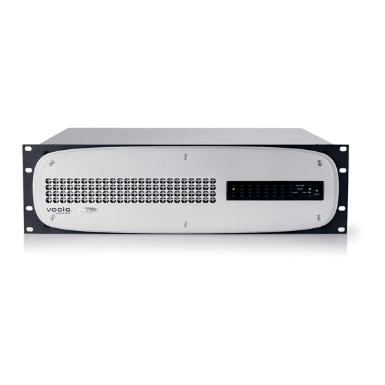
Page 5: System Indicators
VA-8600/VA-8600c FRONT PANEL Figure 1. Front Panel System Indicators amp fault activity signal status power Figure 2. System Indicators Channel Indicators Amp Fault has occurred. Activity is where failover is enabled. -
Page 6: Chassis Indicators
VA-8600/VA-8600c FRONT PANEL Signal -50 dBFS and -3 dBFS, yellow indicates a signal level between -3 dBFS and 0 dBFS, and red indicates clipping. Chassis Indicators Amp Fault depending on the severity of the problem. Flashing yellow indicates a Warning, which means that some aspect of the VA-8600 or VA-8600c failure may occur. -
Page 7: Device Id Switches
VA-8600/VA-8600c REAR PANEL Figure 3. Rear Panel Layout Device ID Switches Power Entrance NM-1 Reset Button solid green once the process is complete. Logic I/O ... -
Page 8: Network Connection
VA-8600/VA-8600c REAR PANEL Network Connection - Table 3. CobraNet interface status LEDs Left LED Right LED Description Green Link established. Flashing Green yellow Flashing Flashing yellow green Flashing yellow AM-600/AM-600c Output the terminals, as this can lead to shorts. Please note: Always check the loudspeaker’s continuous and peak power ... - Page 9 VA-8600/VA-8600c REAR PANEL Loss of power Only faults (e.g., heat sink fault and channel failure fault) trigger the failover mechanism. Warnings indicate abnormal system conditions that do not immediately impair audio and do not trigger the failover mechanism. the redundant VA-8600 or VA-8600c.
-
Page 10: Channel-To-Channel Failover
VA-8600/VA-8600c REAR PANEL Channel-to-Channel Failover Heat Sink fault The wire failover link cable is not required when wiring channel-to-channel failover. Parallel Wiring Redundant Wiring Redundant Primary ... -
Page 11: Va-8600/Va-8600C & Am-600/Am-600C Card Specifications
VA-8600/VA-8600c SPECIFICATIONS Memory: Power: 5.625 MB 110-120 & 220-240VAC 50/60Hz Inputs: 20 bits, 48 kHz, 5-1/3 ms (fixed) Overall Dimensions: Height: 5.25 inches (133mm) Width: 19 inches (483mm) Depth: 17.25 inches (438mm) Connection: RJ45 with shielded Ethernet/PoE cable Weight: (CAT5, CAT5e, CAT6, or CAT7) Chassis: 50 lbs. -
Page 12: Block Diagram
VA-8600/VA-8600c SPECIFICATIONS BLOCK DIAGRAM NETWORK AMPLIFIER MODULE CARD CLASS D SLOT 1 AMPLIFIER SLOT 2 DETECTION SLOT 3 SLOT 4 SLOT 5 SLOT 6 SLOT 7 SLOT 8 TEMPERATURE SLOT 1 CobraNet CobraNet SLOT 2 Audio and SLOT 3 processor control data SLOT 4 SLOT 5... - Page 13 VA-8600/VA-8600c SPECIFICATIONS VA-8600/8600c 115 VAC current draw and heat output modules than the number shown, add 0.1 amps and 37 BTU for each additional module in the chassis. IDLE 1/8 POWER PINK NOISE 1/3 POWER PINK NOISE FULL POWER SINE WAVE Total Output Power VA-8600 (Peak Watts)
-
Page 14: Warranty
VA-8600/VA-8600c WARRANTY terms and conditions set forth below. displays, a nd n ormal w ear a nd t ear o f i tems s uch a s p aint, k nobs, h andles, k eypads a nd c overs a re n ot c overed u nder t his w arranty. All server-based devices are warranted for 3 years only. -
Page 15: Fcc Compliance
FCC COMPLIANCE FCC NOTICE - CLASS B DIGITAL DEVICE NOTE: This equipment has been tested and found to comply with the limits for a Class B digital device, pursuant to Part 15 of the FCC Rules. These limits are designed to provide reasonable protection against harmful interference in a residential as well as in a commercial installation. -
Page 16: Ec Declaration
Biamp Systems Corporation, as manufacturer having sole responsibility, hereby declares that the following described product complies with the applicable provisions of the DIRECTIVES below except as noted herein. Any alterations to the product not agreed upon and directed by Biamp Systems Corporation will invalidate this declaration. Products: Models:... -
Page 17: Eu Rohs Compliant
COMPLIANCE EU RoHS COMPLIANT This Biamp product, including all attendant cables and accessories supplied by Biamp, meets all requirements of EU Directives 2002/95/EC of January 27, 2003, and 2005/618/EC of August 18, 2005, the EU RoHS Directives. An EU RoHS Materials Content Declaration document may be obtained at www.biamp.com...
Need help?
Do you have a question about the VA-8600 and is the answer not in the manual?
Questions and answers