Biamp VOCIA VA-8600 Manual
Digital networked multi-channel amplifiers
Hide thumbs
Also See for VOCIA VA-8600:
- Manual (17 pages) ,
- Operation manual (25 pages) ,
- Manual (9 pages)

Subscribe to Our Youtube Channel
Related Manuals for Biamp VOCIA VA-8600


Summary of Contents for Biamp VOCIA VA-8600
- Page 1 Vocia ® VA-8600/VA-8600c Manual Biamp Systems 9300 S.W. Gemini Drive, Beaverton, Oregon 97008 U.S.A. (503) 641-7287 www.biamp.com...
- Page 2 IMPORTANT SAFETY INSTRUCTIONS...
-
Page 3: Table Of Contents
TAblE OF CONTENTS VOCIA AMPlIFIER 8600/8600c (VA-8600/VA-8600c) . . . . . . . . . . . . . . . . . . . . . . . . . . . . . . . . . . . FEATURES . -
Page 4: Vocia Amplifier 8600/8600C (Va-8600/Va-8600C)
UL listed and RoHS compliant • Covered by Biamp Systems’ warranty Setup and Use The Vocia software provides the interface for configuring and programming the VA-8600 and VA-8600c. The information supplied by this manual relates to hardware installation, physical connections, and device and channel failover concerns. For more details on software... -
Page 5: Front Panel
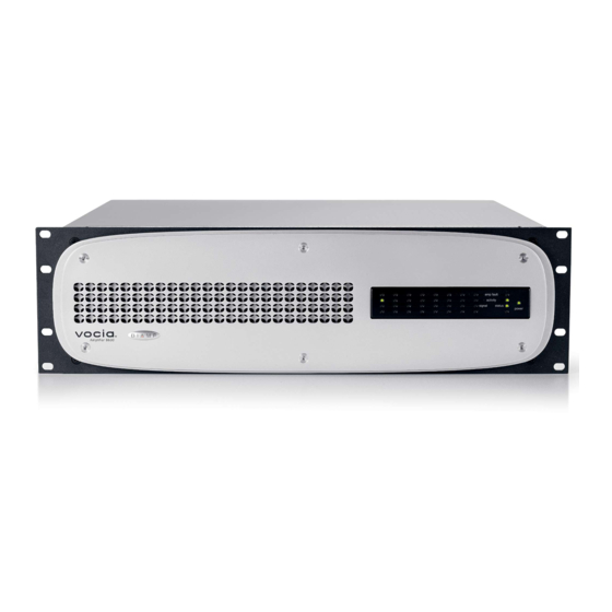
VA-8600/VA-8600c FRONT PANEl Figure 1 . Front Panel System Indicators The LED indicators on the front panel provide information about the function and operational status of the VA-8600 and VA-8600c chassis and any installed AM-600 or AM-600c amplifier modules. Columns one through eight correspond to the eight amplifier module slots. The remaining LEDs correspond to the VA-8600 and VA-8600c chassis. -
Page 6: Chassis Indicators
VA-8600/VA-8600c FRONT PANEl Signal is a tri-color LED that indicates audio signal presence on the channel. Green indicates that the audio signal level is between -50 dBFS and -3 dBFS, yellow indicates a signal level between -3 dBFS and 0 dBFS, and red indicates clipping. Chassis Indicators Amp Fault is a yellow LED that illuminates when a chassis fault has occurred. -
Page 7: Rear Panel
VA-8600/VA-8600c REAR PANEl Figure 3 . Rear Panel Layout Device ID Switches The rotary ID switches are located on the back of the VA-8600 and VA-8600c and give the unit a unique Device ID. The switches are in hexadecimal format. All VA-8600 and VA-8600c units must have a unique Device ID to function properly within a Vocia Paging World (i.e., it is not possible to have two VA-8600 and VA-8600c units with the same Device ID of hex 07). -
Page 8: Network Connection
VA-8600/VA-8600c REAR PANEl Network Connection The VA8600 and VA-8600c are CobraNet devices. All CobraNet routing and bundle assignments are processed by the Vocia devices locally. Vocia makes dynamic use of available bundles in CobraNet. Vocia devices are currently not interoperable with non- Vocia devices. -
Page 9: Amplifier-To-Amplifier Failover
VA-8600/VA-8600c REAR PANEl Amplifier-to-Amplifier Failover Vocia supports one-to-one automatic amplifier failover in case of fault. Failover is triggered by one of the following conditions: • Chassis fault • Channel fault • Loss of power • Loss of CobraNet link • Loss of Logic I/O Only faults (e.g., heat sink fault and channel failure fault) trigger the failover mechanism. -
Page 10: Channel-To-Channel Failover
VA-8600/VA-8600c REAR PANEl Channel-to-Channel Failover In addition to entire amplifier failover, Vocia supports channel-to-channel failover, which is triggered by one of the following conditions: • Heat Sink fault • Short Circuit fault • Channel Failure fault The wire failover link cable is not required when wiring channel-to-channel failover. Parallel Wiring Redundant Wiring Redundant... -
Page 11: Va-8600/Va-8600C & Am-600/Am-600C Card Specifications
VA-8600/VA-8600c SPECIFICATIONS Vocia Amplifier 8600/8600c SPECIFICATIONS Memory: Power: 5.625 MB 110-120 & 220-240VAC 50/60Hz Inputs: 20 bits, 48 kHz, 5-1/3 ms (fixed) Overall Dimensions: Height: 5.25 inches (133mm) Width: 19 inches (483mm) Depth: 17.25 inches (438mm) Connection: RJ45 with shielded Ethernet/PoE cable Weight: (CAT5, CAT5e, CAT6, or CAT7) Chassis:... -
Page 12: Block Diagram
VA-8600/VA-8600c SPECIFICATIONS Vocia Amplifier 8600/8600c Block Diagram NETWORK AMPLIFIER MODULE CARD CLASS D SLOT 1 SLOT 2 AMPLIFIER DETECTION SLOT 3 SLOT 4 SLOT 5 SLOT 6 SLOT 7 SLOT 8 TEMPERATURE SLOT 1 CobraNet CobraNet SLOT 2 Audio and SLOT 3 processor control data... - Page 13 VA-8600/VA-8600c SPECIFICATIONS VA-8600/8600c 115 VAC current draw and heat output To determine the AC line current draw and heat output for the configuration, start by finding the total power for the configured Vocia chassis. Then refer to the column that describes the type of audio levels the amplifier will be producing. If your configuration uses more amplifier modules than the number shown, add 0.1 amps and 37 BTU for each additional module in the chassis.
-
Page 14: Warranty
9. BIAMP Systems shall not be liable for special, indirect, incidental, or consequential damages, including lost profits or loss of use arising out of the purchase, sale, or use of the products, even if BIAMP Systems was advised of the possibility of such damages. - Page 15 COMPlIANCE 14 14...
- Page 16 COMPlIANCE 15 15...
- Page 17 IMPORTANT SAFETY INSTRUCTIONS...
- Page 18 IMPORTANT SAFETY INSTRUCTIONS...
- Page 19 IMPORTANT SAFETY INSTRUCTIONS...
Need help?
Do you have a question about the VOCIA VA-8600 and is the answer not in the manual?
Questions and answers