Advertisement
Quick Links
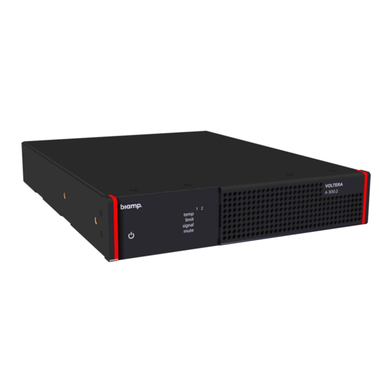
VOLTERA A Series
Installation and Set Up Guide
Product Information Sources
This guide covers the installation and initial set up of the amplifier.
•
Please see the product datasheets on Biamp.com for each Voltera amplifier's
•
specifications.
If you are installing the amplifier in an AV system managed by a Tesira DSP device,
•
you will need a copy of the
Included in the Box
• 0.3" euroblock connector plugs for the amplified outputs (yellow)
o 2 plugs for the 2-channel amps. 4 plugs for the 4-channel amps.
• 3.81mm audio input mating plugs
• Detachable IEC Power cord
• 4 adhesive feet
• 1 single device rack mounting bracket, 1 device rack mounting bracket, and 4
surface-mount brackets.
support@biamp.com
A 300.2 A 600.2 A 300.4 A 600.4 Analog Amplifiers
Tesira Design
Software. See page 17 for details.
www.biamp.com
Advertisement

Related Manuals for Biamp VOLTERA A Series


Summary of Contents for Biamp VOLTERA A Series
- Page 1 Product Information Sources This guide covers the installation and initial set up of the amplifier. • Please see the product datasheets on Biamp.com for each Voltera amplifier’s • specifications. If you are installing the amplifier in an AV system managed by a Tesira DSP device, •...
-
Page 2: Installation Considerations
Installation Considerations • Install the device away from heat sources, such as vents, radiators, heat registers, and stoves. • Do not exceed the maximum ambient operating temperature of 32° - 104° (0° - 40° C). • Avoid installing near water or steam. Device Layout Front Panel Power Indicator Light... - Page 3 Front Panel LED Indicators Power Indicator Green Light Yellow Light The amplifier is off. The amplifier is powered The amplifier is asleep Channel Display Indicators Green Yellow This channel is within safe Fan speed temp Fan speed max temperature medium limits This channel is Channel...
- Page 4 A 300.2 and A 300.2 Back Panels The amplifiers share an identical panel layout Channel 1 gain control 2, 3-pin input Ports Attenuator and High Pass Filter switches Channel 2 output level control Logic input / output connectors 2 Speaker output ports Voltage Control Input A 300.4 and A 600.4 Back Panels Limit / signal indicators...
- Page 5 Included Mounting Brackets 1 Single-Device Rack Mounting Bracket Biamp part number: 548.0468 1 Device Rack Mounting Bracket Biamp part number: 548.0469 4 Surface Mounting Brackets Biamp part number: 548.0470 Voltera Amplifiers Installation and Set Up Guide...
-
Page 6: Installation And Setup Overview
Installation and Set Up Overview Installation Perform the procedures described in the Installation chapter to install the amplifier on a flat horizontal surface or in an AV equipment rack. ✓ Install in a location • Freestanding, page 7 • Surface mount, page 8. •... - Page 7 Install Option: Freestanding Place the amplifier on a flat horizontal surface. 1. Verify the surface is flat and level, and that the amplifier's power cord and connections will be safely out of the way to avoid snagging, yanking, or crushing. 2.
- Page 8 Install Option: Surface Mount Secure the amplifier to a flat surface using the surface mount brackets. 1. Verify the surface is flat and level, and that the amplifier’s power cord and connections will be safely out of the way to avoid snagging, yanking, or crushing. 2.
- Page 9 Install Option: A single amplifier in a 19-inch AV rack Install a single amplifier by itself in an AV equipment rack using the included Single-Device Mounting Bracket and the Device Mounting Bracket. 1. Verify the installation rack space meets the temperature and spacing requirements in the Installation section Consideration on page 2.
- Page 10 Option: Dual devices in a 19-inch rack Install two amplifiers side by side in a standard AV rack using the Device Mounting Bracket included with each unit and two of the included surface mounting brackets. 1. Verify the installation rack space meets the temperature and spacing requirements in the Installation section Consideration on page 2.
- Page 11 4. Fasten the included device mounting bracket to the left side of the amplifier it came with. Then Fasten the included device mounting bracket to the right side of the second amplifier. 5. Place the linked amplifiers into the rack and secure them in place. Advance to the Connect the Amplifier procedure on page 12.
- Page 12 Connect the Amplifier and Set Hardware Settings Connect the amplifier to the input and output devices in the AV systems as well as any voltage control and input / output logics. See the descriptions in this section for the port functions. Adjust the mode settings and turn on the High Pass Filter if required for your system.
- Page 13 Set output Mode and High Pass Filter Switches: Each channel has 2 Mode switches. These can be positioned in 4 combinations to activate one of 4 output modes. The HPF switch is placed in either the ON or Off position. Switch position diagram Mode switches (M) The 4 modes modify the gain structure and limiter thresholds.
- Page 14 Connect speakers to the Output ports Keep the following points in mind. • To minimize power loss, use a speaker cable of appropriate gauge for the load impedance. • Use the supplied euroblock plugs to connect loudspeaker outputs. • If stranded speaker wire is used, be sure to incorporate all strands into the connector, as stray strands can short to the adjacent terminal or chassis.
- Page 15 Optional: Connect logic inputs and outputs (I/Os) Pitch: 3.5mm Pin Functions Note – the pin functions are factory set. • Pin 1 Input: Mute all o Active low • Pine 2 Output: Health output o Fault exists if low • Pin 3 Output: Sleep mode status o Unit asleep if low •...
- Page 16 Plug in the Amplifier Always use the detachable power cord that came with the amplifier or an identical replacement. 1. Attach the power cord to the power receptacle on the back of the amplifier. 2. Plug the connected power cord into the wall power outlet. Voltera Amplifiers Installation and Set Up Guide...
-
Page 17: Amplifier Set Up
Design software. It is typically embedded on digital Tesira system devices and can also be found online. Tesira Help System (Online) • Support Articles Technical support articles for Tesira Software can be found on Biamp’s Cornerstone knowledgebase support site. • Click Here: Tesira - Biamp Cornerstone Training Training courses for Tesira products and system core concepts are available online. - Page 18 Configure the Amplifier in the System For Tesira-DSP-managed systems only. See the Tesira Help system mentioned on the previous page for help configuring the speaker in the AV system. 1. Connect a computer with the Tesira software to the controller device for the AV system the amplifier is now installed in.
- Page 19 Support@biamp.com 9300 SW Gemini Drive Beaverton, OR 978008 USA Warranty: biamp.com/legal/warranty-information Safety & Compliance: biamp.com/compliance April 4, 2023...
Need help?
Do you have a question about the VOLTERA A Series and is the answer not in the manual?
Questions and answers